Help with GM Xtreme 7500 amplifier
The amplifier arrived with problems at the source and I managed to solve the problem with it however there is no wave generation to the output mosfet, I checked the driver card voltages and they are +12, + 5v and -5v, I changed the ir21844s and I still can't get the wave to the mosfet, any other suggestions please
The amplifier arrived with problems at the source and I managed to solve the problem with it however there is no wave generation to the output mosfet, I checked the driver card voltages and they are +12, + 5v and -5v, I changed the ir21844s and I still can't get the wave to the mosfet, any other suggestions please
Post photos of the main and audio driver board in YOUR amp.
There is no 'clock' in most of the 21844 amps so you have to drive a signal into the amp to get signal through the driver board when the amp is not operating normally.
There is no 'clock' in most of the 21844 amps so you have to drive a signal into the amp to get signal through the driver board when the amp is not operating normally.
Thanks for answering Perry
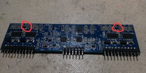
Thanks for answering Perry, I currently do not have a good camera, the photo I have taken of the driver card has been with the cell phone and I mark you in red the 2d transistors that are heating up, I changed them but I still do not generate the wave to the output mosfet, even before it had inserted an RCA signal from a 50 hertz wave generator and nothing yet. Any other suggestions
Thanks for answering Perry, I currently do not have a good camera, the photo I have taken of the driver card has been with the cell phone and I mark you in red the 2d transistors that are heating up, I changed them but I still do not generate the wave to the output mosfet, even before it had inserted an RCA signal from a 50 hertz wave generator and nothing yet. Any other suggestions
Attachments
If Perry is correct, the 50Hz signal reaches the driver card but I don't get any wavelength in the output transistors
Do you see the drive signal on the TL072 and the LM211 outputs?
Do you see the drive signal on the input pin of the driver IC?
Do you see the drive signal on the input pin of the driver IC?
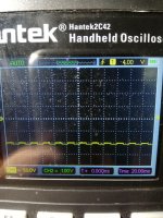
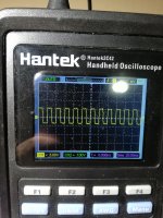
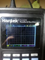
Well, Perry, I checked what you asked for and the square wave attached in the image is the one that comes out of tl072 and lm211, and the negative square wave of -100 volts is the input to the Ir21844s ICs and is the same in all no I had to test this before and I really don't know if it's the right one but in my opinion it should be the same as the one that comes out of tl072 and lm21, correct me if I'm wrong and if it's the reason why there's no wave in the mosfet output
Attachments
Re-check the drive signal for the driver IC with the black probe on the negative rail and the red probe on the input of the IC. Set the scope to 5v/div and the timebase to display 3-4 full cycles.
Do the same thing for pin 2.
Set the scope to DC coupling.
Do the same thing for pin 2.
Set the scope to DC coupling.
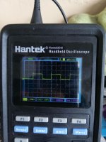
Well I commented that the signal before taking the photo had measured it in the range with 5v / div taking the negative of the rail and showed me nothing, so far all the signal measurements I have taken from the negative rail with the range in I connect dc, and at the entrance of the ICs it shows me nothing only until I put 50v / div as I sent you in the image, for tl072 and lm211 with 5v / div if it shows me the square wave of output, my doubt now Is it at the entrance of the ir21884s ic should I find the same signal that comes out of tl072 and lm211? If I do not receive the signal, what should I check on the driver card to rule out the problem anyway when I arrive at the workshop again I will do what you indicate.
The IC is referenced to the negative rail and why you need to measure with the black probe on the negative rail. Are you sure that you had the black probe on the negative rail and not on ground, instead?
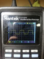
Good morning Perry, I did what you told me but I can't see the entrance signal in the ir21844s. I enclose the images of the result.
What do you think is the cause of the problem since in the eagerness to solve I returned and changed but this time all the integrated Ir21844, the tl072 the lm211 and the lm2903 since I do not have another driver board to test without result besides testing each other One the components inside and outside the plate.
What do you think is the cause of the problem since in the eagerness to solve I returned and changed but this time all the integrated Ir21844, the tl072 the lm211 and the lm2903 since I do not have another driver board to test without result besides testing each other One the components inside and outside the plate.
Attachments
With the black probe of your multimeter on ground, what's the DC voltage on the negative rail where you're placing the black probe for your scope?
Good morning Perry I apologize and you were right I was taking the capacitor's negative reading my mistake, now if I took the reading on the ir21844s from the negative rail whose voltage is -102 volt and gave me the input signal, I installed all the mosfet of output, I introduced a 50 Hz sine wave and the amplifier does not give me audio at the output, I put my probe in the coil before the transistors and I have no square wave signal that you think is the problem now
Attachments
5v is a weak signal but maybe it's what pioneer uses. I don't have anything on a pioneer amp that uses 21844s.
With your black meter probe on the negative rail, post the DC voltage on all terminals of the 21844 IC. Copy and paste the following to post the voltages.
Pin 1:
Pin 2:
Pin 3:
Pin 4:
Pin 5:
Pin 6:
Pin 7:
Pin 8:
Pin 9:
Pin 10:
Pin 11:
Pin 12:
Pin 13:
Pin 14:
With your black meter probe on the negative rail, post the DC voltage on all terminals of the 21844 IC. Copy and paste the following to post the voltages.
Pin 1:
Pin 2:
Pin 3:
Pin 4:
Pin 5:
Pin 6:
Pin 7:
Pin 8:
Pin 9:
Pin 10:
Pin 11:
Pin 12:
Pin 13:
Pin 14:
How about Perry I come back to the workshop today after a few days incapacitated and the first thing I do is turn on the amplifier to take the measures you requested and one of the output mosfet exploded I found myself checking what could happen
If the amp has/had drive problems (especially in the 21844 type amps), it's possible for something like this to happen.
Were you probing any points at the time?
Was the amp powered through a limiter and all semiconductors clamped tightly to the heatsink?
Were you probing any points at the time?
Was the amp powered through a limiter and all semiconductors clamped tightly to the heatsink?
I only connected it to a 12v low-amperage power source and in what turned on the mosfet exploded, it was precisely going to measure the voltages of irs21844 but it didn't give me time. I am currently only working the board, the amplifier is not mounted on the chassis and I have only installed a few mosfet to perform the measurements
- Status
- Not open for further replies.
- Home
- General Interest
- Car Audio
- Help with GM Xtreme 7500 amplifier