I have a fosgate power 1100a2 amp that has dc voltage in one channel .
The left channel works fine, the right channel has 52 volts dc output.
one of the subs seized a coil and took the amp with it.
Would replacing the outputs fix it or is more wrong than I know about?
Ben
The left channel works fine, the right channel has 52 volts dc output.
one of the subs seized a coil and took the amp with it.
Would replacing the outputs fix it or is more wrong than I know about?
Ben
It's rare to have only the outputs fail. Generally it does more damage.
Does it have any shorted output transistors (it probably does but this needs to be confirmed)?
Have any of the emitter resistors opened (significantly higher than 0.1 ohms)?
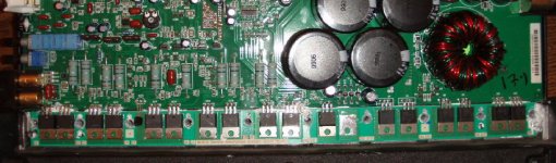
Can you post at least one reasonably good photo of the channel that's failed?
Does it have any shorted output transistors (it probably does but this needs to be confirmed)?
Have any of the emitter resistors opened (significantly higher than 0.1 ohms)?
Can you post at least one reasonably good photo of the channel that's failed?
Have you pulled them to determine if they were shorted?
In the board, they are in parallel and should look like they're all shorted. If you would have checked from the gate to the other legs, then you could see a difference due to the resistance of the gate resistors.
If you still have a few in good condition, you could clip the defective ones and see if there's any DC offset. If not, there may be no other damage.
As a side note, this amp is probably the same as the 500.2 that I recently repaired. I'm not sure what this topology is but don't look for normal audio on the outputs. The audio is riding on the rails. The transistors drive windings on the power transformer and the speaker output is taken 'from the power transformer'.
These are much less common than the normal amps and don't seem to cause as much damage as the common design.
When you pull the outputs, you'll need to double-check the emitter resistors and the gate resistors.
i cant see where the shorts are.? can you get a closer shot?
i never really liked fosgate amps. more people that i talk to have had failed amps
i never really liked fosgate amps. more people that i talk to have had failed amps
I know people like to bash Rockford amps but they make some of the best amps on the market. Many amplifiers will start to give problems after about a year. You'll regularly see problems like:
Shorted transformers/inductors
Failing solder connections
Leads breaking on components (semiconductors, inductors...)
Blown capacitors (often due to one of the previous problems)
Poor quality/noisy potentiometers and switches
You will rarely see any of those problems in Rockford's amplifiers. They are certainly not common problems.
You also have to understand that many of the most abusive people buy Rockford amplifiers because they have a reputation for producing a lot of power.
If a Rockford amplifier is properly installed, you can expect 10+ years of service from it. The only exceptions have been the HD series amps. They used poor quality SMD electrolytics and they leaked electrolyte.
You mean to say Rockford amps can't run at 0.5 ohm mono driving ten 18 inch woofers and deliver 10 tera watts off a single Wal-mart Group 32 car battery 😀 😀 😀
Perry Your absolutely right, especially the call about RF amp owners and what they do to their RF amps in the name of Stupidity.
RF could have added a speaker protection relay and circuit so to prevent voice coil fires when they do fail though, As their older amps at least had internal fuse protection that if untampered with would prevent speakers from becoming flame throwers

But I am all with you Perry on your comments about RF. Just wish they used that speaker relay though, as that channel failing most probably fried his speaker. Seen it a hundred times or more.
Keep up he great work, if he follows your directions his amp will play again🙂
Perry Your absolutely right, especially the call about RF amp owners and what they do to their RF amps in the name of Stupidity.
RF could have added a speaker protection relay and circuit so to prevent voice coil fires when they do fail though, As their older amps at least had internal fuse protection that if untampered with would prevent speakers from becoming flame throwers
But I am all with you Perry on your comments about RF. Just wish they used that speaker relay though, as that channel failing most probably fried his speaker. Seen it a hundred times or more.
Keep up he great work, if he follows your directions his amp will play again🙂
not trying to bash on them. I use to love fosgate back in the late 90's, but seen a few problems since then (probably abusive owners). Most common that i've seen was do to over heating. and a few woofers blown. But to be honest i havent paid much attention to RF since then. I dont dought they may just be the best on the market. i guess im just loyal to my brand😉
outputs are off the board
emitter resistors are ok
I have 2 bad gate resistors the surface mount ones
they are reading 114 and 111 ohms the others read 100 ohms.
emitter resistors are ok
I have 2 bad gate resistors the surface mount ones
they are reading 114 and 111 ohms the others read 100 ohms.
justonemoreamp:
You're right, they should have done something. It would have been easy for them to shut down the supply when a fault occured. I can't understand why they didn't.
ben04srt:
Double-check the emitter resistors. Most meters don't read accurately at low values and you have to be be very careful to make sure you get an accurate reading. For most of my meters, you have to hold the probes on the resistor for a few seconds to let it stabilize. In an amp like this where the transistors will be run hard, it's important that the emitter resistors are very closely matched.
Remember to power up the amp via a 10 amp fuse when you bring it up for the first time. If it blows a 10, you can try a 15 but nothing larger.
impsick:
With the outputs out of the circuit, the gate and emitter resistors are open on one end. The only components that may be able to influence the readings are the protection circuit resistors in parallel with the emitters but their value is generally several hundered times higher than the value of the emitters so they don't have much of an effect.
all 10 outputs are off the board
2 bad outputs
with outputs off board emitter resistors read 0.0 ohms , all 10 of them
gate resistors read
1. 100 ohm
2. 100 ohm
3. 100 ohm
4. 100 ohm
5. 100 ohm
6. 112.3 ohm
7. 100 ohm
8. 104.5 ohm
9. 100 ohm
10. 104.7 ohm
2 bad outputs
with outputs off board emitter resistors read 0.0 ohms , all 10 of them
gate resistors read
1. 100 ohm
2. 100 ohm
3. 100 ohm
4. 100 ohm
5. 100 ohm
6. 112.3 ohm
7. 100 ohm
8. 104.5 ohm
9. 100 ohm
10. 104.7 ohm
Perry, Should I replace the high reading gate resistors or just the outputs and see what happens?
Is there anything else I should check and replace while I have it apart?
Thanks
Ben
Is there anything else I should check and replace while I have it apart?
Thanks
Ben
Of the 3 that are over 100 ohms, only one is technically out of tolerance but I'd change all 3.
If you have the A06s and A56s, you may as well replace them. I don't like changing parts without a good reason but this amp takes quite a bit of time to repair. There's no reason to take a chance on blowing the outputs for $0.40 worth of parts.
Just for fun... Check the ones you pull to see if any failed. Check them carefully to see if any are leaking.
Outputs replaced , a06's and a56's replaced.
Gate resistors replaced
I still have - 52 volts on right channel.
Q221, 222 ,223 all have 13 volts on all three legs.
Gate resistors replaced
I still have - 52 volts on right channel.
Q221, 222 ,223 all have 13 volts on all three legs.
I'll assume that the 100 series parts were actually 200 series parts 217...
What about 216?
What is the voltage on them? If all of the same part number have the same exact voltage, you only need to post two voltages.
Are any shorted? Sometimes a defective driver component can cause new FETs to fail. Other times, they can be damaged when they're being soldered to the insulators.
q216 WAS AT 2.6 volts
the rest of the 9640's were 14 volts
14 volts with the 5 irf640's
I didn't use the mesha board to reinstall them .
the rest of the 9640's were 14 volts
14 volts with the 5 irf640's
I didn't use the mesha board to reinstall them .
- Status
- Not open for further replies.
- Home
- General Interest
- Car Audio
- help with fosgate 1100a2 amp