Hi,
This is my first post, and third speaker design I am working on.
First here's the drivers:
Woofer: Eton 8-402
Midrange: Eton 5-200
Tweeter: Eton 25SD4
All 8 ohm
I am using X-over3 to design my first crossover and came up with the following values:
450hz low to mid, and 3400hz mid to high
Slopes: 2nd order-constant power for the woofer, 1st order solen split -6db for the Midrange, and 2nd order-constant power for the tweeter.
These values give me the flattest response.
I guess my question is do these look good, as this is my first crossover design.
I am really curious about the 1st order filter on the midrange, because if I select a 2nd order filter there is a 5db peak in the graph at 5khz.
Attached is a screenshot of my design in X-over3.
I really appreciate the help! 🙂
Jazz
Attachments
My first advice would be to learn to walk before running. Translated to speakers would be learn to design a 2-way before even thinking to design a 3-way. Moreover if you want to use expensive drivers.
And I can be wrong about the following, because I never used X-over3, but I suspect that this SW can't deal with real FR and box related aspects (diffraction and baffle step). And I'm leaving out also real impedance, if it can't handle also this, it is totally worthless.
So what I'm saying is that I'm a bit suspicious of the outcome. Besides that a 2nd order Hi Pass on the mid should be mandatory in order to tame the resonance peak.
If you want advice, at least provide component values for the crossover.
Ralf
There is free software for speaker design. For example here: software
And here you can find a methodology: http://audio.claub.net/software/DaveDalFarra/Simple%20Loudspeaker%20Design%20ver2.pdf
Thanks so much for your reply!
I do understand the learning to walk before running thing...
I did replace some drivers in a set of old speakers 3 years ago and started learning about 2-way crossover design back then, and when I built my first 3-way speakers I spent months working on designs for a 3-way crossover, and had too many doubts, and went with a factory crossover from Dayton.
I did design a 80hz low pass filter for the subwoofer I built also.
I am also a Musician and Recording Engineer for the past 28 years.
BUT I do not consider myself very knowledgeable about speaker design, just having fun.
For the past year I have been reading page after page of how to design crossovers and figured I'd just dive into the deep end and go for it!
As far as the expensive drivers, I got the two woofers for about a quarter the price on eBay, almost new($139usd for two!), and the Midranges were half-off from Madisound...
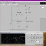
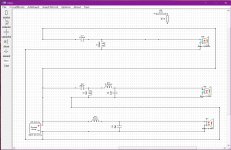
Here are the values for the components:
Tweeter: 3.3uF & .68mH with a l-pad: 3.9ohm & 33Ohm for a 4.1db attenuation to match the other drivers sensitivity.
Midrange: 33uF & .5mH (reversed polarity) X-over3 added a 2ohm resistor in series.
Woofer: 33uF & 3.5mH
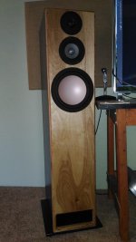
Attached is a picture of my first 3-way speaker design...
Also attached is a screen shot of my crossover design using 2nd order filters on each driver.
You will see the components involved on the upper right of the picture.
Again I am so grateful for you help!!!
I do understand the learning to walk before running thing...
I did replace some drivers in a set of old speakers 3 years ago and started learning about 2-way crossover design back then, and when I built my first 3-way speakers I spent months working on designs for a 3-way crossover, and had too many doubts, and went with a factory crossover from Dayton.
I did design a 80hz low pass filter for the subwoofer I built also.
I am also a Musician and Recording Engineer for the past 28 years.
BUT I do not consider myself very knowledgeable about speaker design, just having fun.
For the past year I have been reading page after page of how to design crossovers and figured I'd just dive into the deep end and go for it!
As far as the expensive drivers, I got the two woofers for about a quarter the price on eBay, almost new($139usd for two!), and the Midranges were half-off from Madisound...
Here are the values for the components:
Tweeter: 3.3uF & .68mH with a l-pad: 3.9ohm & 33Ohm for a 4.1db attenuation to match the other drivers sensitivity.
Midrange: 33uF & .5mH (reversed polarity) X-over3 added a 2ohm resistor in series.
Woofer: 33uF & 3.5mH
Attached is a picture of my first 3-way speaker design...
Also attached is a screen shot of my crossover design using 2nd order filters on each driver.
You will see the components involved on the upper right of the picture.
Again I am so grateful for you help!!!
Attachments
I'm not familiar with this software. I use X-Sim myself. How did you measure the drivers? If you have the frd and zma files X-Sim is real easy to use.
However, you need to have some knowledge first. Designing a crossover aint like dusting crops 😉 For a start that 5Khz peak in the 2nd order xo is because you have the resistor on the output side of the crossover instead of the input side. Having a 1mH inductor in the tweeter circuit isn't a good idea either.
I wish you luck with your design. Somehow though, I can't help feeling this isn't going to sound all that good without some major revisions.
I know it's not the best idea, but I used parameters from the X-over3 database, because I do not have measuring tools yet...
If I end up with a crossover that is even 10% better than a pre-made factory crossover I will be happy!
I will give X-Sim a try.
What measurement tool would you recommend? Would the Dayton Audio DATS V2 do the job?
I plan on taking my time to do this project and am willing to learn as I go...
If I end up with a crossover that is even 10% better than a pre-made factory crossover I will be happy!
I will give X-Sim a try.
What measurement tool would you recommend? Would the Dayton Audio DATS V2 do the job?
I plan on taking my time to do this project and am willing to learn as I go...
Hi Major!
You need electro-acoustical in-cabinet measurements.
So, DATS is great for the driver electricals (impedance, Thielle / Small). It is also very good for measuring crossover components (caps, resistors, coils).
I use OmniMic for the acoustical parts. It's pricey compared to Room EQ Wizard + calibrated mic.
There is some tweak to use REW to do impedance measurements, but I have not tried this.
Best,
Erik
Ok,
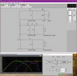
So I did some tweaking, and came up with these two designs.
1st thing is there is now a .65mH coil on the tweeter instead of the 1mH.
I cannot move the resistor on the midrange in the software to the input, but if I omit it the peak around 5k is still there(2nd attachment/design)...could the reason be these are factory specs instead of measured?
These designs look pretty flat, and I know one can't tell till I build, measure and test, I am just wondering if this may be better that a pre-made option...and as a place to start.
Again thanks for your help getting me started in the complex world of crossover design.
I will get measurement tools(DATS) soon. I just want to know if it seem like I even have a grasp on this stuff...
Attachments

A crossover needs to be designed based on the actual in box/baffle FR and impedance of the drivers.For the past year I have been reading page after page of how to design crossovers and figured I'd just dive into the deep end and go for it!
Before designing a crossover, with all the technicalities involved, one has to understand what happens when a driver is placed in a box/baffle. You can read about that, suffice here to say that the FR will change. If you look at the pdf I posted before you'll see what I mean, compare the graph on page 9 to the one on page 12.
This is the reason why a generic crossover won't work, but also why a crossover designed with a SW that doesn't take into account the geometry of the box/baffle and the initial FR/impedance of the drivers won't work either.
So you have 2 routes for doing a design: measurement and simulation.
The measurement route is the easiest one, as you simply measure FR and impedance of the drivers placed in the intended box, but the drawback is that you need to have all the drivers on hand and a box built.
If you don't have the drivers on hand or the box isn't already built, you can perform a simulation. The simulation start taking the usually infinite baffle manufacturer provided FR of the driver, converting this graph into a frd file, then modify the FR simulating the effect of the box/baffle, and finally computing the minimum phase. The resulting file can be used with a crossover simulation SW (for example XSim, PCD, Speaker Workshop), taking into account the relative acoustic offset between the drivers (*). You also need to create a zma file from the impedance profile, then add the box effect for a woofer or midrange. All those steps are described in the pdf posted. If done properly the result of a simulation is pretty close to the reality. I usually simulate, build, measure and tweak accordingly. If you can't measure, rest assured that a proper simulation will work far better than a generic crossover, the only critical point here is that you need to have real graphs from the manufacturer.
If I were in your shoes, I'll throw away X-over3, and start a simulation with proper SW. For sure X-over3 won't provide box/baffle adjustments, and for this reason alone is worthless. I don't know if it knows at least about the infinite baffle FR or the free-air impedance profile of the drivers, out of curiosity could you post a simulation of your 3-way without crossover components, at least for the woofer and midrange?
Ralf
(*) In the crossover simulation SW I suggested, the relative acoustic offset between the drivers can be managed with a distance, instead of an offset inserted directly into the frd files. In this way changing box/baffle geometry you only need to change a value in the crossover SW instead of reworking the whole frd files.
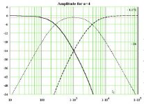
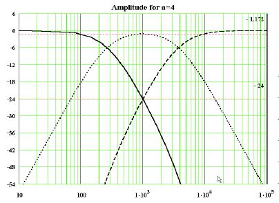
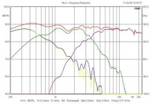
The target Steen Duelund curve for a classic three way is shown below. This actually works at every level including phase. Polarity of drivers is usually best modelled.
Troels Gravesen has two incredibly good and educational projects here:
SEAS-3-Way-Classic
SEAS Kit 503
With a 5" mid, you'll be running into their tendency to a 8kHz cone breakup resonance combined with a rising impedance. Some sort of attenuator in front of the mid often helps get that down. The Celestion Ditton 44 was a quite respectable filter with a 5" mid. Celestion liked a 4th order bass. But second order is OK.
Attachments
Oops. Metal drivers. TBH, I wouldn't touch metal drivers with a bargepole, being bored with building huge complicated crossovers. 😱
Severe Breakup problems. They ring like bells! But the Steen Duelund target curves still apply. Just add notches.
We might look at one of Troels' metal designs to deal with these issues. The main thing is to have some idea where you are heading with a design.
PMS-EXCEL
And target curves are the best idea we have. 😎
Thanks Everyone!
I am going to take a few days and read up on all your great tips, and learn to use X-Sim or Windows Passive Crossover Designer. Can anyone post a link to a program that traces FR specs and converts to FRD files?
I have company here so I may not get back here for a few days...
Thanks!
-Jazz
I am going to take a few days and read up on all your great tips, and learn to use X-Sim or Windows Passive Crossover Designer. Can anyone post a link to a program that traces FR specs and converts to FRD files?
I have company here so I may not get back here for a few days...
Thanks!
-Jazz
Absolutely the best tracing solution.
FPGraphTracer : fprawn labs
If there is anything in the picture that prevents you from getting an accurately traced curve, erase all unnecessary lines around the plot until you get a clean trace, then save it.
FPGraphTracer : fprawn labs
If there is anything in the picture that prevents you from getting an accurately traced curve, erase all unnecessary lines around the plot until you get a clean trace, then save it.
OK,
I decided not to take a break...
First, I would like to say thanks to all of you who kept suggesting using a different program for crossover design, and using FRD files.
Giralfino, when I have more time I will simulate in cab response, May be a few days till I read/understand your great links!🙂
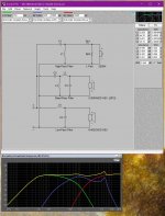
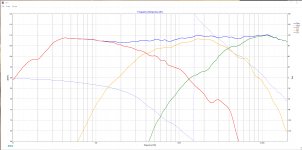
I used FPGraphTracer and traced all manufacturer driver responses, and imported them into X-Sim.
The manufacturer's Woofer FR data sheet ended at 300hz! So I used my box design to estimate response below 300...So the attached graph's woofer response may reflect this(10-20hz).
I then took the values from online generic crossover designers.
I used 500hz and 4000hz for the crossover points.
I also did not put the l-pad on the tweeter because it looked flatter without it(the resistors on top of attaced image 1).
Right now I am not so concerned with in room response because I am going to build a proper studio someday🙂.
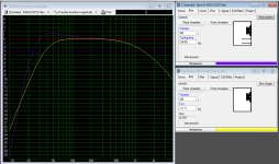
I did attach the current design from X-Sim along with my box design I did in WinISD, with example of a sealed box(in Yellow) and a vented box(in purple).
So here's the questions:
1. Should I use the impedance from the manufacturer specs at the crossover points, or just 8ohms?
2. And how does all this look? I am still learning X-Sim, and I think I got this mostly right.
3. The EBP of the woofers are about 50. Eton said they would work in either vented or sealed, what do you think. I am using with a 12" subwoofer, box tuned to 28hz.
4. I do plan on measuring the drivers with DATS when I get it, I just want to know if it looks like I am getting the hang of X-Sim.
5. Are there any suggestions of components to replace/change/omit in x-Sim?
Should I give up and pay some one to design it for me?🙁😕
I have been doing my best to keep up with all you suggestions but I have been rushing through all this to be with visiting family, that's why I haven't read all the links that were posted(I did scan through them all though).
Thanks!
I decided not to take a break...
First, I would like to say thanks to all of you who kept suggesting using a different program for crossover design, and using FRD files.
Giralfino, when I have more time I will simulate in cab response, May be a few days till I read/understand your great links!🙂
I used FPGraphTracer and traced all manufacturer driver responses, and imported them into X-Sim.
The manufacturer's Woofer FR data sheet ended at 300hz! So I used my box design to estimate response below 300...So the attached graph's woofer response may reflect this(10-20hz).
I then took the values from online generic crossover designers.
I used 500hz and 4000hz for the crossover points.
I also did not put the l-pad on the tweeter because it looked flatter without it(the resistors on top of attaced image 1).
Right now I am not so concerned with in room response because I am going to build a proper studio someday🙂.
I did attach the current design from X-Sim along with my box design I did in WinISD, with example of a sealed box(in Yellow) and a vented box(in purple).
So here's the questions:
1. Should I use the impedance from the manufacturer specs at the crossover points, or just 8ohms?
2. And how does all this look? I am still learning X-Sim, and I think I got this mostly right.
3. The EBP of the woofers are about 50. Eton said they would work in either vented or sealed, what do you think. I am using with a 12" subwoofer, box tuned to 28hz.
4. I do plan on measuring the drivers with DATS when I get it, I just want to know if it looks like I am getting the hang of X-Sim.
5. Are there any suggestions of components to replace/change/omit in x-Sim?
Should I give up and pay some one to design it for me?🙁😕
I have been doing my best to keep up with all you suggestions but I have been rushing through all this to be with visiting family, that's why I haven't read all the links that were posted(I did scan through them all though).
Thanks!
Attachments
The target Steen Duelund curve for a classic three way is shown below. This actually works at every level including phase. Polarity of drivers is usually best modelled.
Troels Gravesen has two incredibly good and educational projects here:
SEAS-3-Way-Classic
Thanks for your help too system7.🙂
The picture of the metal driver speakers were my first project...And your right..they ring a little. That's my main reason I wanted an upgrade.
the Etons are described as '3 layer hexacone sandwich'.
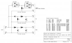
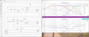
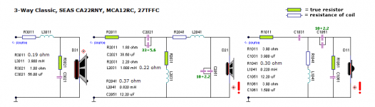
So I read the page about the 3-way Seas kit and modeled the Eton speakers with the crossover design/components on that page.
Attached is what it looks like in X-Sim.
Thanks again for checking all this stuff out for me. I learned a lot in the past few days. still more to read...🙂
Attachments
Eton 5-200 is I think carbon fiber or similar composite material. Breakup is at 6khz but not awful.
Madisound have them on clearance
Madisound have them on clearance
You opted for the short path, unfortunately it is the wrong one. What a baffle does to the FR of a driver is so big that you can't ignore it. The only case you can ignore it is when you design an in-wall speaker, if not you are ignoring at least a 6dB loss of SPL under the baffle step point, making your design totally unbalanced and bass shy. And we haven't even talked about diffraction.Giralfino, when I have more time I will simulate in cab response, May be a few days till I read/understand your great links!
I used FPGraphTracer and traced all manufacturer driver responses, and imported them into X-Sim.
If you don't want to understand now what is described in the pdf I linked, please at least compare the graphs at page 9 and 12 to see what a baffle/box does to the natural FR of the driver. What you did is to use the graph at page 9 when the reality is at page 12.
Impedance does vary with frequency so you have to insert a file (zma) into XSim. For a tweeter you can just trace the impedance graph from a data sheet as you did for FR, for a mid and woofer you should splice the box effect, but for a quick run you can omit it.Should I use the impedance from the manufacturer specs at the crossover points, or just 8ohms?
Ralf
I think you are cooking with gas with that Troels' crossover! 😎
We now know about target curves:
The 8" woofer is a standard sort of 88dB driver, suited to 30L closed box with a Qts of 0.47. Inductance Le is an easy 0.75mH.
The 5" mid is Le 0.55mH, so quite straightforward again. Qts 0.37. 86dB SPL. Perhaps in 5L. Looks flat enough.
The tweeter is an 89dB industry standard.
I reckon Troels' crossover will be fine. Maybe some tiny level adjustment with resistors. But the right idea!
Attachments
Last edited:
I reckon Troels' crossover will be fine. Maybe some tiny level adjustment with resistors. But the right idea!
Thanks! system7, you have given me hope!
I lowered the values of the resistors on the tweeter, from 3.9 for both R2 and R6 to: R2=3ohms and R6 1ohm
I changed C3 on the mid from 12.2uF to 10uF. (seemed to flatten out the mid a bit.)
And changed L4 on the mid from 3.9mH to 3.3mH, which seems to add a bit more bass end(to compensate for baffle step loss.)
I also cleaned up my schematic.
So do these look like good changes?(see attached pics...) It seems pretty good to my beginner mind. (flat, with gradually more db on the woofer)
-Jazz
Attachments


Still don't know much about adding a BSC, do I add it to the woofer or the other two drivers?😱
It seems like I can get a gradual 2-4db rise in the bass down to 40hz or so just by box design.
I do get what is happening and know what baffle step loss is: bass radiates in a omni-directional pattern and so some is lost around the side, to the back, because of the size of the bass wave, I just don't really get how to best compensate for it.
I do plan on having the speakers close to the wall, and I do have a subwoofer. I know that's no excuse for not doing this right from the beginning.
In the BSL calc do I enter the amount in db that I want to compensate for(along with Re and Wb) and then add it before the crossover on the woofer? Then put zobel networks on all the drivers? It seems like to many components, when I thought less were better..😕
I do like my bass though that's why I am so interested in BSL compensation.
-Jazz
It seems like I can get a gradual 2-4db rise in the bass down to 40hz or so just by box design.
I do get what is happening and know what baffle step loss is: bass radiates in a omni-directional pattern and so some is lost around the side, to the back, because of the size of the bass wave, I just don't really get how to best compensate for it.
I do plan on having the speakers close to the wall, and I do have a subwoofer. I know that's no excuse for not doing this right from the beginning.
In the BSL calc do I enter the amount in db that I want to compensate for(along with Re and Wb) and then add it before the crossover on the woofer? Then put zobel networks on all the drivers? It seems like to many components, when I thought less were better..😕
I do like my bass
though that's why I am so interested in BSL compensation.-Jazz
Last edited:
The bass balance is always a bit suck it and see, IMO. The wall does reinforce the bass, so less BSC is needed. Nobody in their right mind uses the full 6dB boost.
Let's hope Troels has got it right. I'd suspect your Le 0.75 bass is lighter than his SEAS woofer. So you put them by the wall! But yours is also a closed box driver, so no port needed. 🙂
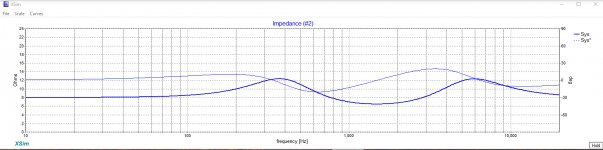
Have a look at the impedance on your crossover. Above 4 ohms with no alarming ripples we hope.
Your tweeter Zobel is way off at 1R/1.5uF. I'd try 7.5R/0.68uF. You can move resistors round a mid filter to raise impedance too. Try them at the front. All good fun.
Let's hope Troels has got it right. I'd suspect your Le 0.75 bass is lighter than his SEAS woofer. So you put them by the wall! But yours is also a closed box driver, so no port needed. 🙂
Have a look at the impedance on your crossover. Above 4 ohms with no alarming ripples we hope.
Your tweeter Zobel is way off at 1R/1.5uF. I'd try 7.5R/0.68uF. You can move resistors round a mid filter to raise impedance too. Try them at the front. All good fun.
- Status
- Not open for further replies.
- Home
- Loudspeakers
- Multi-Way
- Help with first crossover design - 3 way Eton speakers