please kindly help me with a schematic of a power amp of like 500Watt and above at 8 ohms.. using these transistors 2n5551, 2n5401, a1013, tip41, 42, 2sc5200, 2sa1943 (these are the transistors I can find around my local abode ). please all I want you to help me with this. I could not find most of the transistors to the schematics I found on net. and that is why I am pleading for help
You will need to order some other types, the A1013, tip41, tip42 are too low of a voltage to be used in a 500W/8Ω amplifier.
If I am correct. 500W into 8ohm using V2/R=500 meaning V2=4000. This means VRMS=63.24V. Peak is 1.414 X 63.24= 89.43V. You need +/-100V rail!!!! 2N5401, 2N5551, TIP41 and TIP42 all below 200V. Only the two power transistor can do the job. Even the 2SC5200 is cutting too close for comfort at 230V only.
You can do the IPS with the 2N5551 and 2N5401, but you need higher voltage transistors for the VAS and pre driver of the OPS.
You can do the IPS with the 2N5551 and 2N5401, but you need higher voltage transistors for the VAS and pre driver of the OPS.
Last edited:
Bridge amp would work, parallel connected 2N5401/5551 for Vas, c5200/a1943 for drivers as well as outputs.
Bridge amp would work, parallel connected 2N5401/5551 for Vas, c5200/a1943 for drivers as well as outputs.
thanks, but can you help me with any schematic on this.
You will need to order some other types, the A1013, tip41, tip42 are too low of a voltage to be used in a 500W/8Ω amplifier.
what's the best I can get from what I have on ground. and can you help with a schematic? thanks
Better tansistors that 2n5551/and there counter part would be mpsa92/42 for input tail pair..vas stage mje340 and mje350.. simple current mirror vas stage.. even double die mostfet schematics are plenty on the net...
Ive seen amplifiers use 75 to 80 +/- rails giving 500w 4 ohms and brigde mode easy 1000w..
Also if your planing and amp build think about v limitering that all or Most high powered amps...and there Action is to limit drive voltages to safe levels in case the amplifiers speaker output suffers a short..
You dont want to build a project and see all the time/ cash got up in a flash...
If I am correct. 500W into 8ohm using V2/R=500 meaning V2=4000. This means VRMS=63.24V. Peak is 1.414 X 63.24= 89.43V. You need +/-100V rail!!!!
I believe that you have made a simple calculation error. Your output is a sinusoid that has a peak of 63.24 volts RMS. The amplifiers normally discussed here have dual power supplies so each set of output transistors handles half of the output signal. Realizing this, you need half of 63.24VRMS or roughly 32VRMS per side. That means say 45 Volts peak. So, counting for VCE losses, etc., let's just add another 10 Vdc and I would use a +/-55VDC power supply. It seems to me that your transistors should be able to handle that, yes?
Tom are you saying +/- 55DC supply gives 500W into 8R ?
Are you speaking of two amplifiers bridged ?
Waiting for djk to make circuit.
Maybe someone also makes PCB 🙂
Are you speaking of two amplifiers bridged ?
Waiting for djk to make circuit.
Maybe someone also makes PCB 🙂
Last edited:
Yes Vostro, if your amp design swings close to the rail and your power supply has a big enough transformer and filter capacitors. That is non-bridged, single ended.
Hi Guys
Is this a Halloween thread? Lots of scary answers...
Post-10 has the recommended BJTs backwards - 2N5550/2N5400 are more linear than MPSA42/92. The latter have much higher voltage capability and are often used in stages after the input. However, in the common "lin" you can use either with great results.
500Wrms at 8R is 64Vrms, or 90Vpk. With split rails, you need +/-100V at full load, so a hefty PT of 1kVA or more to have sufficient regulation.
To reduce the voltage requirements, you have to go to a bridged amp. In this case, the supplies can be cut in half as each output is driven in opposite directions. The speaker sees the sum of the voltage excursions of the two outputs in absolute terms.
Why do you need so much power?
Have fun
Yes, you are correct, you need the +/-100Volt rails. Sorry about that, d/k what I was thinking.....
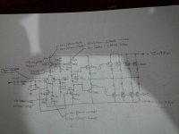
"I could design a very simple but well performing amp for this project if anyone wants it. "
Do you have the time?
I really don't.
What I had in mind was something very simple, like the 300/500W Subwoofer Power Amplifier with the fig.1a output stage.
Using the specified 2N5551/5401 instead, three in parallel for the MJE parts.
Bridged, it will do the required power from ±52V~56V.
Do you have the time?
I really don't.
What I had in mind was something very simple, like the 300/500W Subwoofer Power Amplifier with the fig.1a output stage.
Using the specified 2N5551/5401 instead, three in parallel for the MJE parts.
Bridged, it will do the required power from ±52V~56V.
"I could design a very simple but well performing amp for this project if anyone wants it. "
Do you have the time?
I really don't.
What I had in mind was something very simple, like the 300/500W Subwoofer Power Amplifier with the fig.1a output stage.
Using the specified 2N5551/5401 instead, three in parallel for the MJE parts.
Bridged, it will do the required power from ±52V~56V.
Yes, that is what I had in mind except for a few improvements, most notably an active current source as a load for the VAS.
- Status
- Not open for further replies.
- Home
- Amplifiers
- Solid State
- Help with first amplifier design