Son wants to build an audio amplifier using tubes. I'm a total noob when it comes to tubes. So we got ourselves a EZ80 rectifier and a few other tubes. First things first we wired up the EZ80 to the transformer. 4-5 Pins to 6.3VAC and Pins 1-7 both to 120V AC. The ref wire output of the transformer (120VAC ref) was grounded to the body. When switched on, we only get 62VDC at pin 3 (with body Ref) . Any idea why?.
Are 1 and 7 shorted (half wave rectifier) or connected to opposite ends of a centre-tapped winding (full wave rectifier)? Was pin 3 loaded by something?
EZ80 is a fullwave rectifier where 1 and 7 is the two anodes. 3 is the cathodeSon wants to build an audio amplifier using tubes. I'm a total noob when it comes to tubes. So we got ourselves a EZ80 rectifier and a few other tubes. First things first we wired up the EZ80 to the transformer. 4-5 Pins to 6.3VAC and Pins 1-7 both to 120V AC. The ref wire output of the transformer (120VAC ref) was grounded to the body. When switched on, we only get 62VDC at pin 3 (with body Ref) . Any idea why?.
What is your transformer ? Is it a single 120V winding with (120VAC ref) in the middle ?
Thank you for your replies.
I'm not able to do multiple quotes (New to the forum) but here are my replies.
@batteryman "Smoothing capacitor or inductor?"
- Not yet connected. We just measured the volts using a muti. Pin 3 to Red wire and Black to Plate.
@MarcelvdG "Are 1 and 7 shorted (half wave rectifier) or connected to opposite ends of a centre-tapped winding (full wave rectifier)? Was pin 3 loaded by something?"
- Pins 1 and 7 are shorted and given to 120V DC wire, the Ref wire (0VAC) is connected to plate. We have not loaded anything to the output of pin 3 (Open circuit).
@petertub "EZ80 is a fullwave rectifier where 1 and 7 is the two anodes. 3 is the cathode
What is your transformer ? Is it a single 120V winding with (120VAC ref) in the middle ?
- Transformer is 4 wire out. 0 - 6.3VAC (2A) (2 wires). 0-120VAC (2A) (2 wires).
I think i have wired it for half wave rectification. I will see if i can connect 1 and 7 to Ref and 120V AC. I will post a pic of the connection.
A half-wave rectifier without smoothing ideally produces an output voltage of √2/π times the RMS input voltage. That's about 54 V. You may get somewhat more due to the difference between the unloaded and loaded output voltages of the transformer, or maybe because the meter has some input capacitance. It should go to about 170 V...200 V when you connect a smoothing capacitor, still without load.
Is it a toroidal or an EI transformer? Toroidal transformers are normally not suitable for half-wave rectification.
Is it a toroidal or an EI transformer? Toroidal transformers are normally not suitable for half-wave rectification.
Last edited:
If all you have a transformer with a single 120V winding then drop the EZ90 and connect
a bridge rectifier, this will give app.150V DC
a bridge rectifier, this will give app.150V DC

I've attached the following.
1. The circuit diagram
2. The photos of the transformer
3. Plate with the tube
4. Connection.
I apologize for the low quality of the photos. My son did most of the work and called me only when the problem arose. I think we messed up on the selection of the Transformer as its not center tapped. I'm basically from the solid state school of electronics and I don't understand why my son has taken a fascination towards tubes.
Attachments
1.) NEVER tie rectifier filament to ground!
2.) USE separated filament for rectifier! NEVER tie it another tube's filament!
2.) USE separated filament for rectifier! NEVER tie it another tube's filament!
Have you missed off the anode resistors?I've attached the following.
1. The circuit diagram
2. The photos of the transformer
3. Plate with the tube
4. Connection.
I apologize for the low quality of the photos. My son did most of the work and called me only when the problem arose. I think we messed up on the selection of the Transformer as its not center tapped. I'm basically from the solid state school of electronics and I don't understand why my son has taken a fascination towards tubes.
Should be fine in this particular case. 6X4 is an indirect heated rectifier and the max voltage between a positive cathode to heater is 450V.1.) NEVER tie rectifier filament to ground!
2.) USE separated filament for rectifier! NEVER tie it another tube's filament!
Option 1) Drop the 6X4, use a silicon bridge.
Option 2) Use a "hybrid" bridge, two rectifier silicon diodes + 6X4.
Option 2) Use a "hybrid" bridge, two rectifier silicon diodes + 6X4.
Build this
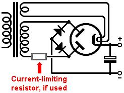
from here ....valvewizard.co.uk/bridge.html
Be sure to size the cap. according to the EZ80 data sheet...Cmax 50uF
Beware EZ80 Iout max....90mA
from here ....valvewizard.co.uk/bridge.html
Be sure to size the cap. according to the EZ80 data sheet...Cmax 50uF
Beware EZ80 Iout max....90mA
Last edited:
1.) NEVER tie rectifier filament to ground!
2.) USE separated filament for rectifier! NEVER tie it another tube's filament!
The EZ80 is designed for use with a grounded heater winding and the resulting large cathode-to-heater voltages.
The OP is total noob for tubes. If he think this is the correct procedure (without knowing the tubes parameters), can do a lot of damage.
Even the EZ80 heater-cathode is such tolerant, other tubes aren't.
Even the EZ80 heater-cathode is such tolerant, other tubes aren't.
As drawn that amplifier section won't work!! There are no load resistors! And your cathode resistors well are.....
What valves are you using? The more data the greater the help.
From what source is your circuit derived.
PS Welcome to vacuum tube audio.The journey is well rewarded 🙂
What valves are you using? The more data the greater the help.
From what source is your circuit derived.
PS Welcome to vacuum tube audio.The journey is well rewarded 🙂
- Home
- Amplifiers
- Tubes / Valves
- Help with EZ80 rectifier