Hi
I have been asked to mend a Hybrid stereo amplifier. It was home constructed many many years ago by persons unknown. It has EL34 running at low anode voltage driving 2 Mosfest in o/p stage. Does anyone have a schematic for such a beast. One channel works fine but looking at the circuit some of the resistors have burnt out (1/8 watt) so be handy to know what the circuit is to fix it.
It has some form of solid state pre amp and an IRF630 Mosfet which I assume is used for biasing ??
Thanks
Rob
Use the working channel to compare voltages to see what they should be.
That should give some clues.
You will obviously have to replace burnt resistors before you can proceed.
Maybe a dim light bulb in the mains to the amp to limit current.
That should give some clues.
You will obviously have to replace burnt resistors before you can proceed.
Maybe a dim light bulb in the mains to the amp to limit current.
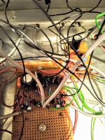
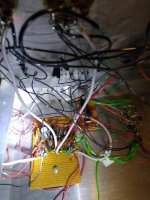
Thanks Nigel ...its a nightmare as the construction is poor ..wires keep falling off. spent time on it last night
.neither channel works properly. One is completely dead and the other is very low gain and changes after time. The cooked resistors have been replaced but something not at all right.
EL34's fine
.one wire fell off and I think its blown one of the mosfets !
It's 10N16 and 10P16 in output, very thin wires ! It was made in the 80's from a magazine or book but so far haven't found the schematic .Looked through ETI archives and searching for Practical Wireless and Wirless World.,.it must be known to someone so any pointers to original would help as its turning into a marathon job.
I would estimate it at 20 - 30 Watts , some form of slow turn on , EL34s run at low voltage. One stage input or amp by semiconductor device unnown, the EL34, them 10N16 10P16 output stage ..and some weird slow turn on biasing
Attachments
Unknown DIY. Redesign will help. Power supply first. Then the circuit for switching on tubes and modes. Tube is a candidate for replacement. Then the MOSFET switching circuit. Usually a follower.
Search Схемы гибридных усилителей низкой частоты. Гибридные усилители
гибридный усилитель - Google Search
Search Схемы гибридных усилителей низкой частоты. Гибридные усилители
гибридный усилитель - Google Search
Last edited: