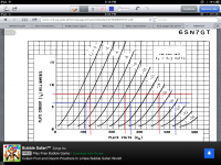
I want to build a CCS as a plate load for a 6SN7 so that I can get a 250 v pp swing with low distortion. It looks like 5 or 6 ma would be about right for my application.
The CCS circuit used in the plate loads shown in this SCHEMATIC use a pair of DN2540s. (My apologies to SY for purloining his drawing). I'm unclear to me how the circuit works and am unable to determine if the current can be sized down to the 5 ma target and what resistor value would be required. I can guess about 600R but I'd prefer to understand it a little better.
Can someone explain the circuit and math of sizing the resistors, please.
Attachments
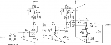
The DN2540 cascode is not a great choice for low currents (under 10mA). A bipolar cascode would work considerably better. There's a very detailed description and design equations in Morgan Jones's "Valve Amplifiers."
Yes SY, the discussion around fig. 2.50 and 2.51 in MJs third edition is essentially my application. No doubt, that's where the idea came from. I don't have a copy of the fourth edition; has Mr. Jones updated his solid state plate load discussion with newer ss devices?
I find the DN2540 circuit, such as used in your schematic, a bit more efficient and would prefer to experiment with it were it not for the low current limitation you describe. Also with B+ near 450 and plate voltage in the 250v range, I'm just a little concerned about smoke at startup.
Matt - this would be a second stage to drive an 845. A cathode follower would make the third stage.
Counter culture - thanks for that link! Have you seen a similar scheme for a source?
Last edited:
captn Dave, surely it can be done with one stage and also DC coupled? Check out the "does the 3a5 have the stones......" Thread.
I am playing about with a GM70 two stage directly coupled design at the moment based on the common base BJT circuit presented by Rod in that thread. It works very, very well. I know the 845 needs a bit more but hey who doesn't over do it with drivers?
Cheers.
I am playing about with a GM70 two stage directly coupled design at the moment based on the common base BJT circuit presented by Rod in that thread. It works very, very well. I know the 845 needs a bit more but hey who doesn't over do it with drivers?
Cheers.
You can treat the circuit as a source or a sink, just put it above or below the load. The LM334Z gives precision control at currents <10mA. A gate stopper resistor might be advisable when using the circuit as a plate load with some other thought given to the possibility of oscillation.
This diagram from the Walt Jung .pdfs linked in the diytube page shows an LM317 similarly employed. Read the Jung .pdfs.
This diagram from the Walt Jung .pdfs linked in the diytube page shows an LM317 similarly employed. Read the Jung .pdfs.
An externally hosted image should be here but it was not working when we last tested it.
I don't have a copy of the fourth edition; has Mr. Jones updated his solid state plate load discussion with newer ss devices?
Yes, he's added the MOSFET cascode as well. The 4th edition is well worth it, IMO, even if you already have the 3rd.
The cascode with 317 and the MOSFET has inferior performance as Jung showed in his follow-up article demonstrating the superiority of the all-MOSFET version first shown in my ImPasse article. The nice thing about the MOSFET cascode is that it's two terminal, so can be used as source or sink. But as the current drops, the impedance suffers.
captn Dave, surely it can be done with one stage and also DC coupled? Check out the "does the 3a5 have the stones......" Thread.
I am playing about with a GM70 two stage directly coupled design at the moment based on the common base BJT circuit presented by Rod in that thread. It works very, very well. I know the 845 needs a bit more but hey who doesn't over do it with drivers?
Cheers.
Matt, I'd love to see your circuit. I am working within the constraints of finding a suitable fix for an existing amplifier. As it happens, the amp is set up as an integrated, with vol pot and switching. So when I say two stages of amplification and a cathode follower, that is including the line stage.
It is quite possible that the constant current sourced triode could drive the 845 without the cathode follower.
Thanks to all for the good ideas and links.
I have tested a few different depletion Mosfets in CCS.
These are the measured Vgs(off), 10 of each:
- DN2540 N3: 2.6v
- DN2540 N5: 2.6-2.7v
- 10M45S: 4.5-4.7v
- 01N100D: 2.7-3v
- 08N100D2: 3.6-4v
I think it makes sense to use a device with a larger Vgsoff as the top Mosfet of the cascode. With a DN2540-DN2540 I couldn't go below 5.5mA, but with a 10M45S-DN2540 I could adjust the CCS down to 0.5mA!
I have tested a few different depletion Mosfets in CCS.
These are the measured Vgs(off), 10 of each:
- DN2540 N3: 2.6v
- DN2540 N5: 2.6-2.7v
- 10M45S: 4.5-4.7v
- 01N100D: 2.7-3v
- 08N100D2: 3.6-4v
I think it makes sense to use a device with a larger Vgsoff as the top Mosfet of the cascode. With a DN2540-DN2540 I couldn't go below 5.5mA, but with a 10M45S-DN2540 I could adjust the CCS down to 0.5mA!
Thanks,
I added a couple to the Mouser order and will check them out too.
I have tested a few different depletion Mosfets in CCS.
These are the measured Vgs(off), 10 of each:
- DN2540 N3: 2.6v
- DN2540 N5: 2.6-2.7v
- 10M45S: 4.5-4.7v
- 01N100D: 2.7-3v
- 08N100D2: 3.6-4v
I think it makes sense to use a device with a larger Vgsoff as the top Mosfet of the cascode. With a DN2540-DN2540 I couldn't go below 5.5mA, but with a 10M45S-DN2540 I could adjust the CCS down to 0.5mA!
I think you can make a cascoded CCS with the IXTP01N100D for currents down to 2-3 mA. Real capacitances are similar to DN2540. Actually Ciss is halved and the others are the same.
- Status
- This old topic is closed. If you want to reopen this topic, contact a moderator using the "Report Post" button.
- Home
- Amplifiers
- Tubes / Valves
- Help with DN2540 CCS design