It is not panels resonating and causing you trouble. Rather think of standing waves in the enclosure due to insufficient damping. The wool clearly is not enough. The internal sizing of the enclosure shows possible first and second order resonances in the 1k, 2k, 1.2k, 2.4k bands. Third order resonance in the vertical dimension is 1.36k. All without effects of damping on the sound velocity of air in the enclosure.
I suspect a standing wave between the enclosure sidewalls that is influencing the cone output. The csd shows the excitation of the resonance mode, first a dip in the driver’s response followed by a ridge on the same frequency. Add more stuffing, at least in the top part of the enclosure.
I suspect a standing wave between the enclosure sidewalls that is influencing the cone output. The csd shows the excitation of the resonance mode, first a dip in the driver’s response followed by a ridge on the same frequency. Add more stuffing, at least in the top part of the enclosure.
Brilliant, thanks Mark, I think you are right - standing waves.
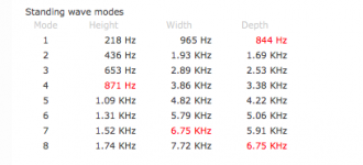
The dimensions and corresponding fundamental standing wave frequencies are:
7" - 960Hz
8" - 846Hz
31" - 218Hz
(the box dimension corresponds to half a wavelength)
This site has a handy calculator: standing waves
This not only highlights the 1.3kHz resonance, but also the resonance observed from the port around 1kHz.
This site has some example measurements with different damping options:
http://www.tonestack.net
Thanks Mark for putting me on the right track. I'll post again once I have added more stuffing and remeasured.
The dimensions and corresponding fundamental standing wave frequencies are:
7" - 960Hz
8" - 846Hz
31" - 218Hz
(the box dimension corresponds to half a wavelength)
This site has a handy calculator: standing waves
This not only highlights the 1.3kHz resonance, but also the resonance observed from the port around 1kHz.

This site has some example measurements with different damping options:
http://www.tonestack.net
Thanks Mark for putting me on the right track. I'll post again once I have added more stuffing and remeasured.
Hi all,
I finally found some time to add some stuffing to the cabinets and re-measure.
The three measurements are:
- original, with lambswool on only the sides of the cabinet
- also with light stuffing in the top two compartments (around the top 2/3 of the cabinet)
- with heavy stuffing in the top two compartments
I haven't weighed the damping material, but to give you an idea, the "light stuffing" required the wool to be teased out to fill the volume, and the "heavy stuffing" has twice the material and fills the volume without it being compressed nor teased-out.
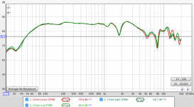
all measured around 25mm from the cone centre.
Slightly surprising to find that the curves are almost identical. This seems to cast doubt standing waves being the issue, or at least insufficient damping being the issue.
Another curiosity is the dip at 1.8kHz of around 10dB which gradually disappears as the microphone is moved away from the centre of the cone.
I am wondering whether to try and download the Martin King Mathcad models and see if there is anything else at play. It seems too much of a coincidence that the resonant frequency hits a standing-wave frequency.
Another option might be to temporarily close-off the lower section and see if the resonance disappears.
Any thoughts very much welcome!
I finally found some time to add some stuffing to the cabinets and re-measure.
The three measurements are:
- original, with lambswool on only the sides of the cabinet
- also with light stuffing in the top two compartments (around the top 2/3 of the cabinet)
- with heavy stuffing in the top two compartments
I haven't weighed the damping material, but to give you an idea, the "light stuffing" required the wool to be teased out to fill the volume, and the "heavy stuffing" has twice the material and fills the volume without it being compressed nor teased-out.

all measured around 25mm from the cone centre.
Slightly surprising to find that the curves are almost identical. This seems to cast doubt standing waves being the issue, or at least insufficient damping being the issue.
Another curiosity is the dip at 1.8kHz of around 10dB which gradually disappears as the microphone is moved away from the centre of the cone.
I am wondering whether to try and download the Martin King Mathcad models and see if there is anything else at play. It seems too much of a coincidence that the resonant frequency hits a standing-wave frequency.
Another option might be to temporarily close-off the lower section and see if the resonance disappears.
Any thoughts very much welcome!
Oh, this is going quite another way I'm afraid. Can the driver itself be suspect here? Some bell-mode resonance or other issue?
I suggested earlier getting it out and measure on a wide baffle made from some scrap panel lying around. Just to eliminate things. Do check driver mounting for leaks and resonances.
Looking back at your measurements in post 32 it is surprising that the response gets almost flat at 150mm measuring distance. So the phenomenon disappears magically. Have you measured the system at more than 1m, preferably with adequate gating > 5ms? And have you saved the last measurements so that you can reproduce the CSD or BD plot?
Thanks for your help, Mark.
Here are the CSD plots - some subtle differences in resonances (actually the heavy damping seems to take longer to decay)
No stuffing (original)
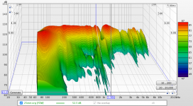
Light stuffing
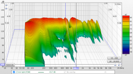
Heavy stuffing
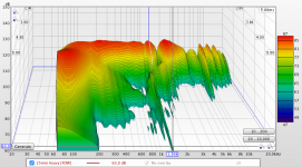
Unfortunately I no longer have the tools to mount the drivers on a baffle - this is an old build that I'm now revisiting after getting a measurement mic and DSP.
Here are the CSD plots - some subtle differences in resonances (actually the heavy damping seems to take longer to decay)
No stuffing (original)

Light stuffing

Heavy stuffing

Unfortunately I no longer have the tools to mount the drivers on a baffle - this is an old build that I'm now revisiting after getting a measurement mic and DSP.
I think the resonance is still there at larger distances (see post 1).
What is interesting is the dip at 1.8kHz, which disappears away from the cone. This suggests a node at the cone centre at this frequency. Can a standing wave occur across the cone?
The cone diameter is about 95mm, which is half a wavelength at 1.8kHz. Another coincidence?
What is interesting is the dip at 1.8kHz, which disappears away from the cone. This suggests a node at the cone centre at this frequency. Can a standing wave occur across the cone?
The cone diameter is about 95mm, which is half a wavelength at 1.8kHz. Another coincidence?
A little research on break-up modes:
where does 'break up' occur on the surface of a cone? -
Techtalk Speaker Building, Audio, Video Discussion Forum
See post 11
"Breakup may occur when these bending waves are reflected from the surround with phase that amplifies the magnitude of the flexing creating a resonance. "
So perhaps the 1.8kHz dip is a reflection from the surround - similar to a standing wave. As is is observed radially it isn't too noticeable away from the cone centre.
The dip at 1.15kHz could be a circumferential wave. (it is the wavelength of the cone circumference)
The Jordan cone is designed from a "microfoil" material which is apparently designed to flex throughout the midband frequencies. I'm speculating whether this creates some unusual vibration modes.
You are on the right track I think. Breaking up is defined as any transducer plane that is not moving like a piston. It happens with any driver and with paper and other 'soft' cone materials it is intended to within the passband. This applies to the Jordans too, as you found yourself. Other metal cones (and domes) are designed to break up outside the passband (given good filtering).
Your CSD plots indicate breakup modes from just above 1kHz. Once a cone starts doing this, it will continue doing so with raising frequency. And so you arrive at a fundamental question: do you like the sound of the Jordan? Then don't bother too much and equalize the sound pressure response by filtering (but stuff the enclosure enough!). If you think it should get better, revert to another driver or (the hard way) try to dampen the cone with the right coating.
Your CSD plots indicate breakup modes from just above 1kHz. Once a cone starts doing this, it will continue doing so with raising frequency. And so you arrive at a fundamental question: do you like the sound of the Jordan? Then don't bother too much and equalize the sound pressure response by filtering (but stuff the enclosure enough!). If you think it should get better, revert to another driver or (the hard way) try to dampen the cone with the right coating.
Thanks again, Mark - very good observation “do you like the sound....”
And the answer is yes, up to a crossover frequency of around 3kHz, which allows attenuation of the higher order breakup modes.
The challenge at the moment is how to define the reference level of the Jordan - should this be at an average level which includes resonances below the crossover, or do we consider these as peaks to be filtered out?
I’m considering using variation in group delay as a objective criteria to decide whether to filter out the peaks due to resonances. If the variation is worse with the filter in place it is probably better to omit it.
Brief update: I ended up fully equalising out the peaks using REWs optimiser, then got interested in time-phase alignment.... perfect transient response and all that jazz.
Big step-up in subjective performance.
S. Harsch XO
Big step-up in subjective performance.
S. Harsch XO
- Home
- Loudspeakers
- Multi-Way
- Help with Diffraction Peak