it's not balanced.In the leach amp schematic: why are caps C6 & C7 only on pin 2 and not pin 3? Surely one would want to remove the D.C. Offset from both pins of a balanced input?
Sent from my iPhone using Tapatalk
The NFB is connected to -IN and thence to Audio Ground.
The input is connected to +IN via that bandlimiting circuit.
This looks like a good Op Amp for my purposes:
http://www.thatcorp.com/datashts/THAT_1200-Series_Datasheet.pdf
But I'm not understanding why the gains are expressed as 0, -3 & -6 dB?
Does that mean that the gains for each model are 1, 0.001 & 0.000001 "Open-Loop Voltage Gain @ DC" respectively? What's the point of having an Op Amp with such small gain?
Also, I am using https://www.circuitlab.com/ to create my circuit diagram (I'll post version 1 as soon as I'm done for some feedback and help - God-willing) and I'm trying to model the THAT 1200 but the datasheet doesn't give me a some of the information I need such as "Open Loop Output Impedance". It does have "Minimum Resistive Load" at 2kΩ. Would that be the same thing?
Also, I need "Gain-Bandwidth Product". Is that the same as "Small Signal Bandwidth" at 22MHz?
(Should I be starting new threads now that I'm getting into the nitty-gritty of building this thing? I would like to keep it going here so that someone following can go through the whole process from concept to finished build.)
Last edited:
I've got a bad case of pain brain today (and not much sleep, either) so back me up, please Andrew. I'm sure Andrew can do a better job explaining balanced impedance concepts than I can, even before I take pain medications.
Take a look at how you are calculating the voltage gain based on each model's stated gain. I think there was an algebra error solving for Vin/Vout. When they say that the gain is -3 dB it means that the voltage gain is ~.5, -6 dB is ~.25.
Remember that the load is the input of the following stage. What that tells you is the chip should be meet its performance when a balanced load is at least 2,000 ohms per leg or a single ended load is at least 10K Ohms.
Good to see you diving into the data sheets early. Too many post questions without looking. It's frustrating responding with "as shown in the data sheet..."
I'm curious why you have chosen this chip and how you intend to use it. I suppose that will be more obvious once you have had a little time with circuitlab.
Your call on whether to start a new thread. Since there aren't a bunch of disparate ideas, why not keep it all here?
I also reckon that this Thread remain dedicated to this project and not be spread to other Threads.
An attenuation to 1/2 voltage is equal to 0.5times and that equals -6.0206dB (most simply say -6dB)
A gain of 2times equals +6dB (but actually +6.0206dB, we just ignore all those extra and inaudible other figures)
But when we quote power in decibels, we find that -3dB = half power and -6dB = quarter power and +3dB = double power +6dB = 4times power.
P = Vac²/Rload
If we double the Vac we get 4 times the power. So +6dB for voltage also equals +6dB for power.
Great - I was hoping to keep the thread going here. But I wanted to check with you guys as I'm relatively new here and wanted to follow the precedent.
The way I calculated it is as follows:
10^(-3) and 10^(-6) because dB is a logarithmic scale.
Sorry - not very good at maths.
I can see that 6 dB = 10 * log(.25) and 3 dB = 10 * log(.5)
therefore to go the other way, it's:
Power Gain = 0.50 = 10^(-3/10)
and Power Gain = 0.25 = 10^(-6/10)
Is that correct?
My logic in using the THAT 1200 is as follows:
From what I understand - and it makes sense on a purely practical level - is that getting matched impedences on a balanced input is a bit hit-or-miss and even slight imbalances will throw the CMRR out. With the bootstrapping of the 1200, by raising the impedance into the Megs, it is able to offset imbalances on the input impedance without raising the overall noise level, leading to better noise cancellation on the input. So - yeah - obviously I'm gonna use it on the balanced input stage.
But I haven't done a lot of homework on Op Amps.
Maybe you guys have some suggestions.
From my understanding I need 3 different types of Op Amp:
1 for the balanced input
1 for the unbalanced iPod input
1 for the overall gain in my mixer
Which brings me to the next point: How much gain should I have? If my input voltage is 2.75163372 peak-to-peak on my balanced input, how much gain do I really need to apply to bring it to a good working level within the mixer? And obviously I think it would be best if it is at unity gain at the output with trims and gain knobs at the halfway mark.
There is probably a really elementary solution to this, but who do I add a trim pot for both left and right without making the signal mono?
I haven't been able to find a 2-gang PCB trim pot and I don't want to have a separate trim pot for left and right.
I haven't been able to find a 2-gang PCB trim pot and I don't want to have a separate trim pot for left and right.
Last edited:
to maintain the interference rejection benefit of balanced impedance connections you MUST get the impedance accurately matched. It cannot be hit or miss. Resistances to better than 0.1% and capacitances (for the higher frequencies) to better than 1%................... - is that getting matched impedences on a balanced input is a bit hit-or-miss and even slight imbalances will throw the CMRR out.
2.75Vpp from a differential source is roughly 490mVac from each of Hot and Cold...................... How much gain should I have? If my input voltage is 2.75163372 peak-to-peak on my balanced input, how much gain do I really need to apply to bring it to a good working level within the mixer? And obviously I think it would be best if it is at unity gain at the output with trims and gain knobs at the halfway mark.
500mVac on each pole is equivalent to 980mVac between the poles and that is equivalent to 2.77Vpp between the poles.
This would be specified as 1V. The ac is often dropped from the Vac.
Your source is putting out ~1Vac
What are you expecting at the next stage/receiver?
The difference is made up by applying extra gain.
But do you need extra gain?
to maintain the interference rejection benefit of balanced impedance connections you MUST get the impedance accurately matched. It cannot be hit or miss. Resistances to better than 0.1% and capacitances (for the higher frequencies) to better than 1%.
Right. I have control over impedances within my own unit, but I don't have control over the cables that ar made or the quality of the DJ mixer that is used at the input stage. That is why I thought this op-amp would be a good idea. Your thoughts?
2.75Vpp from a differential source is roughly 490mVac from each of Hot and Cold.
500mVac on each pole is equivalent to 980mVac between the poles and that is equivalent to 2.77Vpp between the poles.
This would be specified as 1V.
Why is it specified as 1V?
The ac is often dropped from the Vac.
Your source is putting out ~1Vac
What are you expecting at the next stage/receiver?
The next stage would probably be a power amplifier
The difference is made up by applying extra gain.
But do you need extra gain?
I don't know. That's why I'm asking you. 😀
Any ideas about the 'trim knob' situation and how to trim L and R with just 1 trim knob?
You have to check the impedance matches. If they are crap then change them.Right. I have control over impedances within my own unit, but I don't have control over the cables that ar made or the quality of the DJ mixer that is used at the input stage. That is why I thought this op-amp would be a good idea. Your thoughts?
Cables add a bit of capacitance. But if you research the cable topic for screened twisted pair you will find the DIFFERENCES between the two poles is small enough to be ignored in all competently manufactured balanced cables.
I wrote it out for you.Why is it specified as 1V?
2.77Vpp is the same as 1Vac which is often written as 1V
what signal is needed at the balanced impedance input of your power amplifier?The next stage would probably be a power amplifier....I don't know. That's why I'm asking you. 😀
No idea.Any ideas about the 'trim knob' situation and how to trim L and R with just 1 trim knob?
The way I understand your trim pot requirement it is just another attenuator. For single ended signals you can use a dual pot. Balanced signals would require a quad pot that must be much more tightly matched than are commonly available.
Since the trim pots are for basic system level matching it might make sense to switch an l-pad attenuator. For example, to drop a pro level signal to consumer level, just drop the appropriate number of dB. To bring the iPod input up to consumer line level, add a few dB.
In case it's not quite obvious, Andrew is asking what signal is needed to drive your amplifier to full power?
The way I understand your trim pot requirement it is just another attenuator. For single ended signals you can use a dual pot. Balanced signals would require a quad pot that must be much more tightly matched than are commonly available.
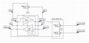
I think the best idea then would be to use an op-amp similar to the LM386 which has 2 x GAIN pins between which one can place a resistor in order to determine output gain. However, unlike the LM386, I would need an op-amp with 2 cop-amps within the same package, but which are both controlled with the same set of GAIN pins. In this way, if I placed a 1-gang trimpot between the pins, I would be able to change the gain of the stereo signal simultaneously. Then of the outputs, I could have a dual-gang pot which would then be my GAIN knob - on the front of the unit.
I have attached a screenshot to give a better idea of what I mean.
So - do you guys know of a suitable op-amp for said purpose? And if not, would you suggest I ask the rest of the diyAudio community with a new thread requesting suggestions for op-amps for this purpose?
Since the trim pots are for basic system level matching it might make sense to switch an l-pad attenuator. For example, to drop a pro level signal to consumer level, just drop the appropriate number of dB. To bring the iPod input up to consumer line level, add a few dB.
I think the level I have settled on is as follows:
Balanced & Unbalanced Input range: -10dBV (0.9 Vpp) to +10dBu (6.9 Vpp); Centre position = 0.42 dBu = -1.79 dBV = 2.3 Vpp
But that doesn't make much sense does it? That would mean that I need to decrease the +8 dBu down to -10dBV before doing anything with it. Seems like a bit of a waste of voltage.
Seems it would make more sense to bring the iPod voltage up to +8dBu so that both the balanced and unbalanced input voltages are matched. Right?
Sorry - I hope you don't mind: I'm kinda working it out in my head as I write this. Helps to have you guys listening in on my thoughts.
Anyway, it doesn't really matter what the input voltages are, as long as they are matched for balanced and unbalanced. Right? And as long as the the trimpot gives the same range of gain for each input and as long at 12 o'clock on the trimpot outputs the same voltage for each input. You guys following me?
In case it's not quite obvious, Andrew is asking what signal is needed to drive your amplifier to full power?
Thanks. Learning so much now that I feel like my head is exploding, so I need the obvious stated at this point.
So again, I want this to be a unit that anyone can plug in and it'll work with most power amplifiers on the market.
I think the best bet would be to match the specs of the Pioneer DJM900 master output which is +8 dBu with a 5 ohm output impedance.
That makes sense right because often these DJ mixers are plugged straight into a power amplifier at a bar or club.
What do you guys think?
Thanks so much for your help. This whole process that I'm going through and all the questions you guys are asking are really helping me to flesh this thing out and to understand exactly what I require.😛
Attachments
- Status
- Not open for further replies.
- Home
- Source & Line
- Analog Line Level
- Help with designing an active, balanced input mixer with crossfader