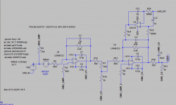
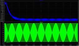
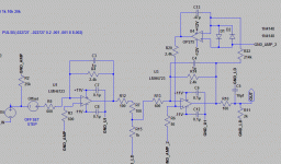
I've built a preamp around the LME49713 current feedback op amp. The results so far look very good. I added a DC servo to manage the DC offset - which varies from -2mv to 19mv depending upon the volume pot setting. I used the LME49720 op amp for the servo. I simulated the following circuit and it show the servo correcting the offset. The actual circuit changes the offset to 32mv regardless of the volume pot setting. So, is some respects, it's working in that it's making the DC a constant value, but, it's not the 0 volts expected. Advice and critique would be greatly appreciated.
Regards,
Ken
I used the LMH6723 current feedback op amp model for the 49713 and the op275 for the 49720.
Regards,
Ken
I used the LMH6723 current feedback op amp model for the 49713 and the op275 for the 49720.
Attachments
Should the DC servo for an inverting amp not also be inverting and act on the non-inverting input?
It is also advisable to use anti-parallel diodes between the servo's input pins to avoid overvoltage.
It is also advisable to use anti-parallel diodes between the servo's input pins to avoid overvoltage.
I've been reading up on CFB opamps too, and there's two things I've picked up on:
1. (This is taken directly from Linear Tech's "CFB Do's and Don'ts") "DO NOT PUT A SMALL CAPACITOR FROM THE INVERTING INPUT OF A CURRENT FEEDBACK AMPLIFIER TO ANYWHERE, ESPECIALLY NOT TO THE OUTPUT." The "all caps" is their form. Note your C4.
2. I don't believe a CFB opamp should ever be used in an inverting mode, due to the difference in input impedances. (This part hasn't been stated implicitly, but no app notes show an inverting circuit.)
Hope this helps.
Artie said:I've been reading up on CFB opamps too, and there's two things I've picked up on:
1. (This is taken directly from Linear Tech's "CFB Do's and Don'ts") "DO NOT PUT A SMALL CAPACITOR FROM THE INVERTING INPUT OF A CURRENT FEEDBACK AMPLIFIER TO ANYWHERE, ESPECIALLY NOT TO THE OUTPUT." The "all caps" is their form. Note your C4.
2. I don't believe a CFB opamp should ever be used in an inverting mode, due to the difference in input impedances. (This part hasn't been stated implicitly, but no app notes show an inverting circuit.)
Hope this helps.
Artie,
I read the app notes as well, so, I didn't explain the cap shown parallel with the gain resistor if for the simulation only, it represents the capacitance of the resistor and traces.
Audioman54 who helped develop the 49713 recommended the inverting configuration - like you I had the same impression. Have a look at the thread in the solid state forum "National Op amp inflation" you'll see his comments and my measurements from the preamp.
I tried simulating the it with the servo output going to the non-inverting pin of the preamp opamp and it offset the entire sinwave by about 4v positive.
Other thoughts - thanks.
Ken
With the servo inverting?klewis said:I tried simulating the it with the servo output going to the non-inverting pin of the preamp opamp and it offset the entire sinwave by about 4v positive.
I took the output from R21 and connected it to the non-inverting pin of U3 in the simulation and disconnected it from the inverting pin. All of the aforementioned was done with the simulator, not the physical circuit.pacificblue said:
With the servo inverting?
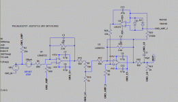
I think you have a good point here, though the non-inverting input behaves quite differently on a CF opamp compared to VF opamp. I'll post another schematic.pacificblue said:Should the DC servo for an inverting amp not also be inverting and act on the non-inverting input?
It is also advisable to use anti-parallel diodes between the servo's input pins to avoid overvoltage.
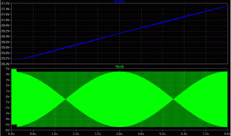
Since the non-invert resistor has a much smaller value on a CF amp vs VF amp, I thought I might reduce the resistor values in the servo by an order of magnitude in the inverting servo. I've made a run with this configuration and it seems to correct the offset. I will try to build this configuration tonight and see what happens.
Attachments
Well, that didn't work> I got +4.3v DC offset when i fired it up. Tried several resistor values in place of r22, though r20 was set at 1k.
The more I think about it the more I come to the conclusion that a DC servo won't work with a current feedback amp. The DC servo gives a voltage feedback, not a current feedback. You will have to inject a current into the non-inverting input to achieve an offset compensation.
I. e. connect a potentiometer (trimmer) between + and -. To the wiper connect a small capacitor to ground and a resistor to the non-inverting input. With the potentiometer you set the voltage to which the capacitor will be charged. The capacitor discharges through the resistor and amplifier's input stage to ground, which leads to the compensation current. Adjust with the potentiometer.
I. e. connect a potentiometer (trimmer) between + and -. To the wiper connect a small capacitor to ground and a resistor to the non-inverting input. With the potentiometer you set the voltage to which the capacitor will be charged. The capacitor discharges through the resistor and amplifier's input stage to ground, which leads to the compensation current. Adjust with the potentiometer.
pacificblue said:The more I think about it the more I come to the conclusion that a DC servo won't work with a current feedback amp.
Seems to work plenty well with AD815 judging by the number of servoed designs...
analog_sa said:
Seems to work plenty well with AD815 judging by the number of servoed designs...
Analog,
can you point me to a one?
thanks,
Ken
pacificblue said:The more I think about it the more I come to the conclusion that a DC servo won't work with a current feedback amp. The DC servo gives a voltage feedback, not a current feedback. You will have to inject a current into the non-inverting input to achieve an offset compensation.
I. e. connect a potentiometer (trimmer) between + and -. To the wiper connect a small capacitor to ground and a resistor to the non-inverting input. With the potentiometer you set the voltage to which the capacitor will be charged. The capacitor discharges through the resistor and amplifier's input stage to ground, which leads to the compensation current. Adjust with the potentiometer.
Pacificblue,
Thanks for thinking about this. I got a servo to work, the values for the resistors are quite different from servos for vf amps. But the resistor value changes move the Fc way up to around 1Khz. Which then boost the lower frequencies - not good. So, I'm currently simulating a third stage in the servo to bring the voltages back up... it's sort of working. I'll build one next weekend.
Ken
any luck?
klewis,
I started playing with CFB op amps, too. Any luck on your servo after a year? I contacted Nat Semi and they sent me right back over here. ha!
klewis,
I started playing with CFB op amps, too. Any luck on your servo after a year? I contacted Nat Semi and they sent me right back over here. ha!
by wrapping the CFA in the fedback loop of a good "audio" op amp you can get your "DC Servo" action for free and gain other advantages from the multiloop composite amplifier
compensation is a little more challenging if you want to use more of the CFA gain in the loop but doing so "improves" the performance of the input op amp as well
Walt Jung describes several "multiloop" composit amplifier circuits in his "Op Amp Applications" book
http://www.analog.com/static/import... Amp Applications Book (PDF)/P2 Ch6_final.pdf
- Status
- Not open for further replies.
- Home
- Amplifiers
- Chip Amps
- Help with DC Servo for Current Feedback Opamp
