Allen, when I say "Let's try to nail down the basics of my measurement scheme and driver positions in Vituixcad", this is my way of saying I need help to understand this. I get that it's important to understand this, this is why I asked the very specific questions earlier about measurement scheme.What is important is that you understand this and use it when you develop your measurement scheme.
I usually take everything people write here literally. I'm not sure @DcibeL meant something else, I can't speculate about this.Lament, I dont believe should take it literally when Dcibel says it's not good practice, I think this was said in haste to show you that you were missing something. Understand that the delay is always something for you to watch, and you can make it work any way you choose to measure. For example, the problem is not fixed even if you measure at each driver's axis because thats not the listening distance either. Unless you plan to simulate the distances. One way is to use virtual driver placement options. Therefore Dcibel's way works for his method and not necessarily for all methods.
Is there a measurement scheme that would allow all driver positions in Vituixcad to be fixed at 0?
I must admit it can be hard to follow you Allen, you are cryptic at times 🙂I'm not sure this method is what you are looking for today. I simply tried to help you see the bigger picture because I have seen when people read step by step instructions they still have many questions. So when it becomes clear to you then you will branch out and find better ways, but until then you might want to take a simpler approach.
Member
Joined 2003
Not sure why I'm being quoted here replying to someone else in another thread, but since you are bringing up using a constant mic location for all individual driver measurements..Lament, I dont believe should take it literally when Dcibel says it's not good practice, I think this was said in haste to show you that you were missing something. Understand that the delay is always something for you to watch, and you can make it work any way you choose to measure. For example, the problem is not fixed even if you measure at each driver's axis because thats not the listening distance either. Unless you plan to simulate the distances. One way is to use virtual driver placement options. Therefore Dcibel's way works for his method and not necessarily for all methods.
With the use of VituixCAD, CTA-2034-A and reliable results regardless of speaker type, size, etc, yes, measuring drivers from a single mic location is not good practice. With a dual or semi-dual measurement configuration in mind, there is no situation where measuring individual drivers off axis (at the tweeter axis) makes sense. The "problem" is not only one of delay between drivers, but also SPL over distance, and accurate results for power/DI chart and directivity plots, which is why I say the simulation is locked in to a response that may not be an accurate representation of the response at listening distance. DI/power spinorama will also be incorrect unless the mic location is 2m+ which is impractical for most indoor measurements.I usually take everything people write here literally. I'm not sure @DcibeL meant something else, I can't speculate about this.
Is there a measurement scheme that would allow all driver positions in Vituixcad to be fixed at 0?
To answer your question, just follow the measurement instructions for VituixCAD, it doesn't require very expensive gear and is a simple method that overcomes the limitations of leaving the mic in a single location. Following this process, and assuming your speaker has a flat baffle, z axis offset remains at 0 for all drivers, tweeter x,y coordinates at 0, and other driver x,y coordinates are entered relative to the tweeter location.
With full set of on and off-axis measurements completed at driver axis, listening distance can be easily adjusted in VituixCAD with accuracy, simply done by interpolating off-axis measurement data and calculation of SPL adjustment over distance to listener. The main benefit here is accurate response result at normal listening distance of 2m+ using measurement data taken at a shorter ~1m.
To be honest I'm finding this thread quite difficult to follow, can you elaborate a bit on the specific problems / questions you have in the measurement / design process?
Attachments
Hi DcibeL,Not sure why I'm being quoted here replying to someone else in another thread, but since you are bringing up using a constant mic location for all individual driver measurements..
I referenced your post in the Vituixcad thread because you provided some excellent feedback that cleared up some questions for me. I got very confused when Allen then disputed this.
Thank you, this is exactly how I have done my measurements and set driver positions in Vituixcad.With the use of VituixCAD, CTA-2034-A and reliable results regardless of speaker type, size, etc, yes, measuring drivers from a single mic location is not good practice. With a dual or semi-dual measurement configuration in mind, there is no situation where measuring individual drivers off axis (at the tweeter axis) makes sense. The "problem" is not only one of delay between drivers, but also SPL over distance, and accurate results for power/DI chart and directivity plots, which is why I say the simulation is locked in to a response that may not be an accurate representation of the response at listening distance. DI/power spinorama will also be incorrect unless the mic location is 2m+ which is impractical for most indoor measurements.
To answer your question, just follow the measurement instructions for VituixCAD, it doesn't require very expensive gear and is a simple method that overcomes the limitations of leaving the mic in a single location. Following this process, and assuming your speaker has a flat baffle, z axis offset remains at 0 for all drivers, tweeter x,y coordinates at 0, and other driver x,y coordinates are entered relative to the tweeter location.
Allen has been very kind and patient with his contributions here, but I think we may have been talking past eachother.With full set of on and off-axis measurements completed at driver axis, listening distance can be easily adjusted in VituixCAD with accuracy, simply done by interpolating off-axis measurement data and calculation of SPL adjustment over distance to listener. The main benefit here is accurate response result at normal listening distance of 2m+ using measurement data taken at a shorter ~1m.
To be honest I'm finding this thread quite difficult to follow, can you elaborate a bit on the specific problems / questions you have in the measurement / design process?
So I fully understand that you find the thread hard to follow 🙂
Initially I wanted some response to my preliminary crossover simulation that I attached in my first post. I also attached FRD and ZMA files.
Do you think this looks okay DcibeL, or do you see any room for improvement (I would be very surprised if not)?
Member
Joined 2003
Ok, now I am up to speed 🙂
Given the posted data, first suggestion is that you need response to 180 degrees in order to fill in the power and DI data. Measurements are incomplete, so only on-axis response is useful. If you use D2608, with the amount of off-axis data available, only listening window will be useful.
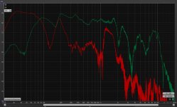
Your woofer response files are showing a major problem between 100-200Hz, and are also not showing typical baffle step response for drivers measured on a speaker baffle, so I don't have much confidence in your splicing of near/far measurements.
Second suggestion is to provide a higher order filter on the tweeter than just a single cap. But first you need to provide the software with good data, so focus on the measurement and response processing procedure first.
Given the posted data, first suggestion is that you need response to 180 degrees in order to fill in the power and DI data. Measurements are incomplete, so only on-axis response is useful. If you use D2608, with the amount of off-axis data available, only listening window will be useful.
Your woofer response files are showing a major problem between 100-200Hz, and are also not showing typical baffle step response for drivers measured on a speaker baffle, so I don't have much confidence in your splicing of near/far measurements.
Second suggestion is to provide a higher order filter on the tweeter than just a single cap. But first you need to provide the software with good data, so focus on the measurement and response processing procedure first.
Last edited:
Hi DcibeL,Ok, now I am up to speed 🙂
Given the posted data, first suggestion is that you need response to 180 degrees in order to fill in the power and DI data. Measurements are incomplete, so only on-axis response is useful. If you use D2608, with the amount of off-axis data available, only listening window will be useful.
this response is exactly what I needed, thank you!
I am aware of this. I was a bit lazy, not having a turntable this was a tedious process. So I decided to take a shortcut this first time, and tweak and evolve this crossover over time when I get more experience. I just need something to get me started. But I suppose I can still simulate directivity to 60 degrees with woofers and D2608 tweeter.
For the Morel tweeter I only have on-axis measurments at the moment.
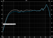
This is a good point. I have attached an image showing my nearfield measurements of woofers and port. Green = Woofers, Red = Port.Your woofer response files are showing a major problem between 100-200Hz, and are also not showing typical baffle step response for drivers measured on a speaker baffle, so I don't have much confidence in your splicing of near/far measurements.
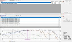
And also one of the Merger tool in Vituixcad, I may have messed up something here.
I will try to simulate a second order filter for the Morel.Second suggestion is to provide a higher order filter on the tweeter than just a single cap. But first you need to provide the software with good data, so focus on the measurement and response processing procedure first.
Attachments
Member
Joined 2003
Neafield response should be the immediate area of focus. Area from 100-200Hz should be smooth, that may be cabinet reflection, is there no stuffing in your cabinet? Port response showing a big peak at 200Hz is also of some concern. If you load in just nearfield and port response to the merge tool, no diffraction, the result should closely resemble your enclosure model. For the sake of simplifying the merge process, you can always skip the port response, it's not going to have much influence on a crossover design >1kHz.
Beyond that, I would recommend processing each upper and lower woofer responses individually. Diffraction response is fine, but just for the sake of argument, since nearfield response is for a single driver, diffraction simulation should also only include single driver, and distance = typical listening distance of 2-3m. Not that it will make much difference either way, but 10m distance is a bit odd to see here. You will find that making this adjustment has little effect to the diffraction response of interest for this task, <1kHz.
Beyond that, I would recommend processing each upper and lower woofer responses individually. Diffraction response is fine, but just for the sake of argument, since nearfield response is for a single driver, diffraction simulation should also only include single driver, and distance = typical listening distance of 2-3m. Not that it will make much difference either way, but 10m distance is a bit odd to see here. You will find that making this adjustment has little effect to the diffraction response of interest for this task, <1kHz.
Last edited:
There is definitely stuffing in the cabinets, but I will see if I can rearrange it or experiment with different types of stuffing.Neafield response should be the immediate area of focus. Area from 100-200Hz should be smooth, that may be cabinet reflection, is there no stuffing in your cabinet? Port response showing a big peak at 200Hz is also of some concern. If you load in just nearfield and port response to the merge tool, no diffraction, the result should closely resemble your enclosure model. For the sake of simplifying the merge process, you can always skip the port response, it's not going to have much influence on a crossover design >1kHz.
It looks like I have some more work to do with the nearfield measurements before moving on, I'm going to remeasure this.
And thanks for the tip about skipping port response, since it's also on the back it will have even less influence on the higher frequencies.
I just copied the example from kimmosto in his tutorial here, where he used 10m distance. I will try this using listening distance instead.Beyond that, I would recommend processing each upper and lower woofer responses individually. Diffraction response is fine, but just for the sake of argument, since nearfield response is for a single driver, diffraction simulation should also only include single driver, and distance = typical listening distance of 2-3m. Not that it will make much difference either way, but 10m distance is a bit odd to see here. You will find that making this adjustment has little effect to the diffraction response of interest for this task, <1kHz.
When you say processing each woofer individually, you mean the farfield responses? I did measure each on their own axis, and imported them individually to the merger tool.
Wrt the diffraction response, the nearfield response is for a single driver but bass response includes both drivers. Both drivers were connected, but one driver was isolated with a pillow in front of it. I'm a bit confused about only using one driver for diffraction response.
Member
Joined 2003
In retrospect I think what you've done for diffraction is fine. Both woofers included in diffraction model to create average diffraction in the far field, and 10m distance is used to avoid response null from differing driver distance to mic. Keep on as you are, near field response is the only real point of interest to address.There is definitely stuffing in the cabinets, but I will see if I can rearrange it or experiment with different types of stuffing.
It looks like I have some more work to do with the nearfield measurements before moving on, I'm going to remeasure this.
And thanks for the tip about skipping port response, since it's also on the back it will have even less influence on the higher frequencies.
I just copied the example from kimmosto in his tutorial here, where he used 10m distance. I will try this using listening distance instead.
When you say processing each woofer individually, you mean the farfield responses? I did measure each on their own axis, and imported them individually to the merger tool.
Wrt the diffraction response, the nearfield response is for a single driver but bass response includes both drivers. Both drivers were connected, but one driver was isolated with a pillow in front of it. I'm a bit confused about only using one driver for diffraction response.
Hello.Hi,
please critique my first attempt at a crossover for a Living Voice Auditorium clone I'm working on.
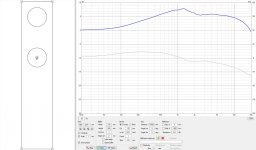
The speaker is a 2-way MTM with 2 x Vifa C17 6.5" midwoofers and initially a Scanspeak D2608/93000 tweeter. I got better measured response with Morel CAT 378 tweeters, so I used those in this simulation. I measured all drivers according to the Vituixcad procedure, however I only have on-axis response for the Morel since I just got it. So I have to leave out power response and directivity for now. The last image shows the response of the drivers without filter, for reference.
I'm a little wooried about the broad overlap area between 2khz-5khz, is this any reason for concern? I think the phase tracking in this area looks pretty good though how to clone voice.
Also would the large impedance hump centered around 3khz cause any issues?
Designing a commersial speaker is a something including the speaker elements parameters and the volume/size of the enclosure. That and meeting desired retail price still resulting in profit. Guess You all know this, not unique for speakers - applies basically anything on the shelf.
My question or thinking is regarding the crossovers, as a example the (famous) Rogers LS3a where a small near field monitor used by BBC (UK) and still can be bought as a clone. But the crossover in these are very complex and big, lots of coils, condensors and resistors and are, according to what i learned not the most efficient speakers around. Never heard them but have absolutely no doubt they are amazing.
Anyway, to make this long story shorter: "Less is more" (old saying) and if applied on crossovers AND speaker elements, spending more time on matching the elements to each other and the box/volume/type of enclosure (closed/vented/horn/open baffle/...) must (?) lead to less "manipulation" via added components, which inturn create problems just been added (phase shifts at x-over frq etc).
Summarizing since I seemed to lost myself, possibly You aswell; Crossovers, is less more?
Depending on the design-
It can take a simple nudge, or it can take a hammer. What the wanted end goal is, is up to the builder.
It can take a simple nudge, or it can take a hammer. What the wanted end goal is, is up to the builder.
Hi... is this thread still alive..? I would absolutely love to see the final crossover design! with the specs/schematic.. I have some real living voice auditorium obx (outboard crossovers) that are missing... the crossovers.. So i need to make some. It has the same wifa 17 drivers and a scanspeak revelator tweeter. This thread is like a dream come true after days of looking around. It seems Lament has not posted recently though.. Allen,..? does anyone know what's up, or have a copy of his amazing construction? IS ANYBODY OUT THERE....................!?! You could change my life!
thanks
daniel
thanks
daniel
Hi Allen, thank you very much for your work so far!
It is very obvious where the first reflection is in the impulse window, if that is what you mean 1ms vs 5ms. Do you think there may be errors in the measurements? This is my first time following this procedure, so I may very well have done something wrong here.
There are no published factory plots to compare with, and I haven't found any reviews with measurements either.
Anyway, the LV uses the Scanspeak D2608, not the Morel CAT378. Maybe you could try to do something with that as well?
I agree, the simulation below does not look very good. Do you feel this is an improvement over my simulation? The crossover region sure looks better on your simulation though, not the large overlap I got on mine.
But to my understanding, the scaling in Vituixcad is a measure taken to avoid double dealing this effect?
I had to read the last part a couple of times, but I think I got it 🙂 So basically you are saying, as long as I use my measurement protocol with Vituixcad I will be okay, and a less powerful software without this feature would require measuring both drivers at the same time?
Yes, that was it. Ok, this doesn't have the right feel and I suspect the response is not what it should be. Does 1ms look different to 5ms? Does your measurement look anything like the factory plot?
View attachment 1043528
Many people think that.. but it should only be that way under certain circumstances or you'll double deal the effect.
You see, vituixcad can simulate the interaction of the two drivers by considering their spacing. On the other hand you can measure that very effect by measuring the two at the same time. It's one or the other.
Yes, I believe Lament went on to do something with horns.
I don't know the original crossover other than I might find by searching, but I do know how to do a D'Appolito style cross. If you're going to take a shot at designing it, there are many ways you can approach it. If you'd like guidance, it would help greatly to choose a method first.
I don't know the original crossover other than I might find by searching, but I do know how to do a D'Appolito style cross. If you're going to take a shot at designing it, there are many ways you can approach it. If you'd like guidance, it would help greatly to choose a method first.
I'm not sure D2905/9500 diagram version will be of much help but why don't you give a call to Kevin or Lynn Scot from LV and ask for help ? Speaker is discontinued and they are down to earth and pleasure to deal with people.
I believe he got rid of Zobel circuit in OBX flagship. Wire is a single run of solid enameled conductor. I think 16 gauge. These speakers are notoriously hard to set up and fussy of the amp .They require long wall positioning free from adjacent surfaces. They are voiced for classical repertoire and there were some complaints of HF roll- off. 9500 is a 90dB tweeter and quoted efficiency was 94 dB.
Oh , forget polars , graphs and all that measuring shebang. They are mostly designed " by ear ".
Thanks guys. I did contact Living Voice but did not hear back, and quite possibly this stuff is in the realm of trade secrets or just too small fry. But lots of great info on this site so hopefully I can muddle through-
I guess I'm ready, I found a schematic that should get me near enough for my half deaf untrained ears. My remaining wonder, after having my head filled with lots of kind suggestions on the reddit diy audio group (that lead me here) is that maybe the dsp route might make more sense, assuming there were some wave guide type info I can just replicate from recorded numbers of the original. Both options are new to me and seemingly would cost about the same, that is to say around $200, as I would be buying the most budget options for the crossover build. And then I can update it later.when you're ready..
If I get bitten by the diy bug I might do both, and have them alongside each other, though perhaps that would need a switch so the circuits are separate.
I found a guy's page where he sold some of these speakers with upgraded crossovers so it seems he knows exactly what all the numbers are but I didn't see a way to contact him from .
In a way, I'd be delighted to be told what to do- as things stand I'm going to work through the diagram I have and figure out the components I need to order and then do that. I'm in the uk looking for budget options, the a.i generated crossover design I 'made' found pretty affordable bits.
It would certainly be good to get the show on the road! thanks Allen
Ok, you have a circuit. That moves you forward so let's look at that.
AI that looks through all the available crossover information is likely to produce something confused and inappropriate, so check it first and expect to work on it as you listen.
For a person who likes to find their sound by listening and trying things, DSP could make that quicker.. and for a person who isn't familiar with electronics, it can open doors for them.
AI that looks through all the available crossover information is likely to produce something confused and inappropriate, so check it first and expect to work on it as you listen.
For a person like myself it makes no difference. I will get the job done either way. The important parts of crossover design are the same in both cases.after having my head filled with lots of kind suggestions on the reddit diy audio group (that lead me here) is that maybe the dsp route might make more sense,
For a person who likes to find their sound by listening and trying things, DSP could make that quicker.. and for a person who isn't familiar with electronics, it can open doors for them.
Thanks for the reply. I sent you a message ..let's look at that
Slightly overwhelmed by your problem solving gusto! After I've drawn up a total sourcing of components and costs I'll have a look at pricing on a suitable dsp scenario I guess. There were some boards for £60 each that seem to fit the bill with the perhaps dreaded bluetooth but also a 3.5mm imput that I could fairly easily fit inside the speakers that link to some software. In my head I don't know how you join the two together to be in timing especially over the 'air' but most of this stuff seems like magic to me anywhere so... But as a 1st timer the passive crossover could be a nice project to get me started.
My hifi audiophile friend was dismissive of going the dsp route but his well trained ears may well notice things I would never. I like the idea of trying to be faithful to the original design, which so far as I can understand things, is more likely going the passive route and accepting that it won't really be like the original vs guessing my way through dsp software. If a bunch of pre measured stats were available would that make the dsp more accurate than a budget passive replica?
No, the DSP will not be more accurate with this speaker as long as the person designing the crossover knows what they are doing.`
I respect what your audiophile friend has to say about an analogue source. Digital can be done well, there are good and bad examples of both.
For you, the difference is small compared to not having a working crossover 😉
I respect what your audiophile friend has to say about an analogue source. Digital can be done well, there are good and bad examples of both.
For you, the difference is small compared to not having a working crossover 😉
- Home
- Loudspeakers
- Multi-Way
- Help with crossover for Living Voice clone