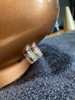
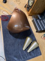
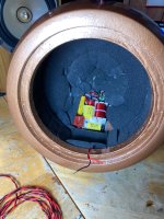
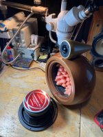
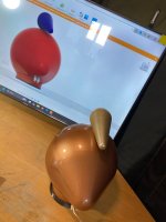
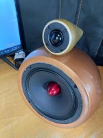
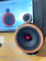
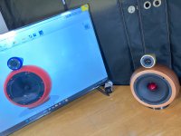
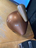
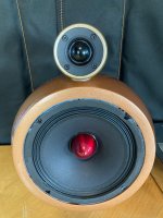
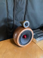
I have some progress made on my speaker 🔊 pods. Figured I would show my first prototype.
Attachments
-
 IMG_1586.jpeg841.5 KB · Views: 45
 -
 IMG_1587.jpeg977.9 KB · Views: 40
 -
 IMG_1613.jpeg993.3 KB · Views: 36
 -
 IMG_1626.jpeg896 KB · Views: 40
 -
 IMG_1627.jpeg880.6 KB · Views: 39
 -
 IMG_1629.jpeg1,006.6 KB · Views: 42
 -
 IMG_1633.jpeg559.8 KB · Views: 43
 -
 IMG_1634.jpeg617.1 KB · Views: 42
 -
 IMG_1635.jpeg719 KB · Views: 38
 -
 IMG_1636.jpeg691.8 KB · Views: 46
 -
 IMG_1639.jpeg674.7 KB · Views: 37
 -
 IMG_1640.jpeg649.4 KB · Views: 41
 -
 IMG_1641.jpeg905.7 KB · Views: 47
 -
 IMG_1642.jpeg950.1 KB · Views: 42

Nice work. The pod speaker certainly looks the business!
I see you've incorporated, at least for now, the 'Amazon' crossover .
What are your initial impressions regarding the sound produced by the prototype?
I see you've incorporated, at least for now, the 'Amazon' crossover .
What are your initial impressions regarding the sound produced by the prototype?
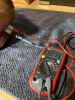
I’ve been waiting for the sealer to dry. It’s supposed to dry clear when it’s done but I did play with them a little at low volume and need to spend more time with it. I have been comparing to by Paradigm S2 signature reference. I will try and do some rough measurements between the two. My initial impression is that there is more midrange present and that they are louder overall but the tweeter is not as loud as the S2. I set the switch on the tweeter to the mode which does not bypass the output capacitors on the xover.
I think we predicted that the full range driver is a touch overpowering compared to the tweeter. It has more definition in the midrange and seems more broadband in the mods than the S2.
I think we predicted that the full range driver is a touch overpowering compared to the tweeter. It has more definition in the midrange and seems more broadband in the mods than the S2.
Paradigm S2 Signature Reference original Stereophile review:
Paradigm S2 signature reference measurements
You can find the measurements and plots for it while I try and get some recording gear setup. I will try to do the measurements in TrueRTA. These speakers are hard to beat for the size. I have tried probably 20 or 30 pairs of various high end bookshelf for my desktop speakers over the years and have settled on these for about 10 years now then I started digging myself a hole designing my own speakers.
I took 3 sets of crude relative measurements using my M-Track Plus on lowest gain input setting connected to a AKG C1000S setup 1 foot away from each speaker and centre between both 2 way drivers. On each test I moved the fader to the appropriate speaker so that only that speaker output was being measured.
Teardrop:
.jpeg")
Paradigm S2:

.jpeg")
Teardrop baseline noise floor level:

Teardrop 1khz tone test:

Teardrop pink noise sweep:

Paradigm Signature Reference S2 Measurements:
S2 Baseline noise levels:

S2 1 KHz test tone:

S2 pink noise sweep:

I'll leave it to the birds.
Thank for watching!
Teardrop:
Paradigm S2:
Teardrop baseline noise floor level:
Teardrop 1khz tone test:
Teardrop pink noise sweep:
Paradigm Signature Reference S2 Measurements:
S2 Baseline noise levels:
S2 1 KHz test tone:
S2 pink noise sweep:
I'll leave it to the birds.
Thank for watching!
I'm sorry, but the graph labeled Teardrop pink noise sweep looks impossibly flat. Even with the 10 dB/grid line, there is zero evidence of the baffle step at the low end of the woofer or tweeter range, there is no apparent diffraction artifacts from the very sharp edge of the cylindrical front baffles for each driver.
https://pearl-hifi.com/06_Lit_Archi...ec_51/4445_Acoustical_Engineering_3rd_Edn.pdf
See page 23 for baffle diffraction of a driver on the end of a cylindrical baffle, which is what you have built.

There is no variation around the crossover frequency, which would be expected as this was not a custom crossover that matched the drivers and compensated for the impedance etc. Even if everything I mentioned was compensated for with a custom 20 component crossover, the reflections from the desktop and back wall would have added some large variation in the response. I think that graph looks like a loop back from input to output of a sound card or something. I could be totally wrong and you have accidentally built a near perfect speaker.

Even if you mount a driver on a sphere with out sharp edges, there will be a baffle step.
https://sound-au.com/bafflestep.htm
https://pearl-hifi.com/06_Lit_Archi...ec_51/4445_Acoustical_Engineering_3rd_Edn.pdf
See page 23 for baffle diffraction of a driver on the end of a cylindrical baffle, which is what you have built.
There is no variation around the crossover frequency, which would be expected as this was not a custom crossover that matched the drivers and compensated for the impedance etc. Even if everything I mentioned was compensated for with a custom 20 component crossover, the reflections from the desktop and back wall would have added some large variation in the response. I think that graph looks like a loop back from input to output of a sound card or something. I could be totally wrong and you have accidentally built a near perfect speaker.
Even if you mount a driver on a sphere with out sharp edges, there will be a baffle step.
https://sound-au.com/bafflestep.htm
Last edited:
I've made a terrible blunder in at least one of the above plots. I was also skeptical about the response. Thank you for calling me out. I have re-run the noise floor and pink noise tests to the best of my ability; as follows:
Teardrop baseline noise floor test @ 1ft.

Teardrop pink noise test @ 1ft.

Paradigm S2 Signature Reference baseline noise floor test @ 1ft.

Paradigm S2 Signature Reference pink noise test @ 1ft.

All of these plots were taken at 50% volume on the soundcard mixer. I used M-Track Plus as the audio capture interface and it was set to lowest input gain.
Teardrop baseline noise floor test @ 1ft.
Teardrop pink noise test @ 1ft.
Paradigm S2 Signature Reference baseline noise floor test @ 1ft.
Paradigm S2 Signature Reference pink noise test @ 1ft.
All of these plots were taken at 50% volume on the soundcard mixer. I used M-Track Plus as the audio capture interface and it was set to lowest input gain.
If the measurement is not gated the diffraction effect (partially) evens out with the rest of reflected room sound.there is no apparent diffraction artifacts from the very sharp edge of the cylindrical front baffles
So with an off the shelf text book sort of crossover that wasn't matched to a pair of off the shelf drivers the response is better than the Paradigm S2. Ok.
I didn't want to offend you, just wanted to point out that diffraction effects get less pronounced or may even disappear when using non-gated measurements.the response is better than the Paradigm S2. Ok.
I should have made that clear ...
stv: No offence taken! All potential course corrections are welcome. The neat thing about audio is that it is complex and has many facets to keep track of.
I certainly have seen the difference when switching between the measurement modes. I will have to go experiment with Arta and pay close attention to the baffle diffraction frequency area when changing analysis modes (gated vs long term measurement) . I know the diffraction effects are minimized with very close mic position. With the microphone out three times the baffle width or more I would expect to start seeing some contribution from the edge diffraction.
I also tend to do sweeps rather than the pink noise - PSD type measurements. With the microphone at 1 foot from the speaker I wouldn't expect the room to have much influence other than that very reflective desktop.
I have not looked to see what pattern that microphone has. If it was a narrow super cardioid pattern, or something else, that would certainly make a difference relative to the omnidirectional measurement microphone I use.
I do not relate the performance to cylinder or the sphere... I think it is a compromise of both? Unless, I do not understand your considerations and associated physics. I think I need guidance on further tests to conduct but it sounds very good to my ear better than I expected and seems to be producing midrange frequencies that I cannot hear well with the S2. Guitar, synth, piano and vocals are much more forward and the bass response appears to be very close; almost the same. S2 outshines a little with stuff like tamborine impulses and upper end definition probably due to their special beryllium dome tweeter assembly which has a pretty large metal assembly and heatsink attached to it. I had to take it apart on one speaker and replace the diaphragm (Paradigm charged me $60 for a new one which I thought was a steal) on one of the speakers when I received them due to shipping damage on that part. I remember it to be attached to heavy cast metal work. The whole top metal part that is on top of the speaker is coupled to it with thermal compound. FWIW.I'm sorry, but the graph labeled Teardrop pink noise sweep looks impossibly flat. Even with the 10 dB/grid line, there is zero evidence of the baffle step at the low end of the woofer or tweeter range, there is no apparent diffraction artifacts from the very sharp edge of the cylindrical front baffles for each driver.
https://pearl-hifi.com/06_Lit_Archi...ec_51/4445_Acoustical_Engineering_3rd_Edn.pdf
See page 23 for baffle diffraction of a driver on the end of a cylindrical baffle, which is what you have built.
View attachment 1382553
There is no variation around the crossover frequency, which would be expected as this was not a custom crossover that matched the drivers and compensated for the impedance etc. Even if everything I mentioned was compensated for with a custom 20 component crossover, the reflections from the desktop and back wall would have added some large variation in the response. I think that graph looks like a loop back from input to output of a sound card or something. I could be totally wrong and you have accidentally built a near perfect speaker.
View attachment 1382550
Even if you mount a driver on a sphere with out sharp edges, there will be a baffle step.
https://sound-au.com/bafflestep.htm
Last edited:
I'm glad that you were able to achieve the high quality sound. I was just pointing out that when any speaker driver is mounted centered on the end of a cylinder or round baffle with a sharp edge, exactly as you did with your speaker, there is a predictable diffraction that occurs when the sound waves round that sharp edge. The edge diffraction produces a sort of second source of sound that is delayed from the direct sound such that it causes peaks and dips in the response. The text describes how to predict it. It happens at the lower frequency range covered by a driver where it is projecting sound very wide and not beaming. So even a speaker driver with a perfectly flat response will have it's response modulated by the baffle it is placed in. Depending on the crossover frequency, those ripples in response related to the baffle diameter may fall outside of the range the driver is used. There is a Baffle tool in VituixCAD that lets you model complex baffle shapes and see the effect. Visaton Boxsim models baffle effects as well, but is limited to rectangular boxes. It's interesting to move a driver around on a baffle and change the size to see what happens in these software tools.
Over the years I have played around with rounded baffles.

Drivers mounted flush on an Ikea bowl.
To minimize the baffle effects I have put drivers on the surface of spheres to avoid sharp edges.


This large taught me that the sphere diameter has an upper frequency cut off due to the delay from each driver.

This line array had a very smooth response

Here I effectively made a wide section of the pipe to allow mounting the midrange and tweeters.
Here I was avoiding sharp edges with 4" half round. This was a contest winner. This was inspired
by speakers by Grimm Audio, the LS1.

Last year I printed these 6" spheres with 20 drivers. Again, looking to avoid any sharp edges.
Over the years I have played around with rounded baffles.
Drivers mounted flush on an Ikea bowl.
To minimize the baffle effects I have put drivers on the surface of spheres to avoid sharp edges.
This large taught me that the sphere diameter has an upper frequency cut off due to the delay from each driver.
This line array had a very smooth response
Here I effectively made a wide section of the pipe to allow mounting the midrange and tweeters.
Here I was avoiding sharp edges with 4" half round. This was a contest winner. This was inspired
by speakers by Grimm Audio, the LS1.
Last year I printed these 6" spheres with 20 drivers. Again, looking to avoid any sharp edges.
@olsond3 I appreciate your craftsmanship and I remain humbled by your experience and expertise! I am likely not going to build anymore speakers unless I can 3d print them in carbon fibre and not finish them. I do not have a proper shop to sand and paint and it creates a huge amount of overhead of time and makes a mess. I want to finish my 10" sub adapter pod to try and test the full design.

I'm working to redraw the tweeter horn to improve the balance. I like the sound of the speaker but it is a little lossy in the high end compared to the S2. I think I can attribute this to the Dayton ND25FA-4 driver. I need a little help choosing a better tweeter. I found NHP25F-4 that is not as flat but has better efficiency with similar form factor (footprint).
https://www.parts-express.com/pedocs/specs/275-108--dayton-audio-nhp25f-4-specification-sheet.pdf
It is similar fit to the original so it wouldn't be hard to modify the tweeter horn to make it fit. I am wondering if there is a better choice for my design?
Also, I am rounding the curves of the baffles to be more sphere-like for the tweeter and midrange enclosures. I am not sure if this offers better response than the flat ones but we can test it.
Last edited:
The way you describe this is similar to the way some would describe baffle step.
- Home
- Loudspeakers
- Multi-Way
- Help with crossover choice for my 2 way pod speakers 🔊