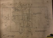
Wow, so many great responses! Building a new enclosure is a possibility. I have removed everything including the speakers so that I can do some cosmetic restoration / modifications to the cabinet. Here is a picture of the whole schematic to help answer questions about the horn wiring. I am a complete novice when it comes speaker design / wiring so please dumb it down for me, thank you for the time and understanding as I dive into this and try to learn on the fly.
Attachments
Thanks, Mike, I'm always curious about these old driver combinations.
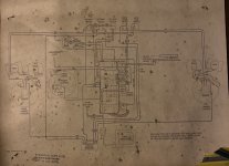
However, my eyesight isn't what it used to be, so any possibility of a higher resolution image?
However, my eyesight isn't what it used to be, so any possibility of a higher resolution image?

Thanks Dave!
I've been staring at that complication of switch and extension speaker terminals that makes it difficult to trace the circuit, and I think you've got it right.
The mid is clearly wired in parallel with the woofer via the series capacitor as per convention.
33uF is too large to high pass the horn tweeter so I surmise, that being a Motorola console, the horn tweeter is a Motorola capacitive piezo device which provides its own high pass function.
What do you think?
There MUST be a capacitor in series with tweeter.
4.7 - 3.3 - 2.2 uF, pick one.
"Should" be inside the cabinet, but in this case we have a Tweeter Mute switch, it probably lives there or along the path.
If original drivers are kept, I would also keep the original enclosures, as-is , only splitting them away from the center cabinet, unless it´s repurposed for some useful function.
Books? Bar?
Not much modern design will improve those high Q speakers, besides stuffing some damping material to walls, and maybe stapled to perforated back, so it becomes some kind of aperiodic resistive load.
Would also build some housing for the midrange, midrange modulation under "big brother" Bass pressure is a distinct possibility.
And would drive the whole shebang with a 15+15W amp, not more.
Plan B would be to keep just the empty enclosure for aesthetics, and fit inside any modern speaker *cabinet* that fits in.
EDIT:
Easy to check, just measure DC resistance across Tweeter terminals.
4.7 - 3.3 - 2.2 uF, pick one.
"Should" be inside the cabinet, but in this case we have a Tweeter Mute switch, it probably lives there or along the path.
If original drivers are kept, I would also keep the original enclosures, as-is , only splitting them away from the center cabinet, unless it´s repurposed for some useful function.
Books? Bar?
Not much modern design will improve those high Q speakers, besides stuffing some damping material to walls, and maybe stapled to perforated back, so it becomes some kind of aperiodic resistive load.
Would also build some housing for the midrange, midrange modulation under "big brother" Bass pressure is a distinct possibility.
And would drive the whole shebang with a 15+15W amp, not more.
Plan B would be to keep just the empty enclosure for aesthetics, and fit inside any modern speaker *cabinet* that fits in.
EDIT:
*Might* be, although all alnico drivers hint at an earlier age, preceding Piezos but ... who knows?I surmise, that being a Motorola console, the horn tweeter is a Motorola capacitive piezo device
Easy to check, just measure DC resistance across Tweeter terminals.
Last edited:
There's no sign of such a capacitor. Don't you think it could be a piezo tweeter, JMF?There MUST be a capacitor in series with tweeter.
4.7 - 3.3 - 2.2 uF, pick one.
"Should" be inside the cabinet, but in this case we have a Tweeter Mute switch, it probably lives there or along the path.
Just edited my answer considering that. 🙂
In any case:
1) Tweeter wires go outside the picture, it may easily have needed capacitor (if dynamic) at the amp or front panel side.
Very common in Bass amplifiers, again sporting a tweeter kill switch , many have said switch at the front panel or very accessible, for the Bass player it´s just another EQ option.
Some cheesy powered cabinets include the capacitor in the main amp PCB, which has 3 wire outputs: Ground (common) - Woofer (straight/flat) -Tweeter (through cap)
They save some assembly time that way for the added cost of a foot of extra wire 🙂
As a local example, this is our famous "Kioto Sound Multiplier", TDA2040 powered , claiming 70W RMS so not THAT exaggerated, driving a 4 ohm 10" Woofer and a cheap cone tweeter .
Bottom edge shows Parlante/speaker outs:
* Par Masa is Speaker ground
* Par B(ajos) : Speaker B(***)
* Par T(weeter) is self explaining.
Notice output is taken through NP/BP 4.7uF x 63V electrolitic.
This guy easily sells 20X what I do, (or more), his powered speakers are designed to reamplify Phone outputs ,or MP3, CD, cassette players, laptops, whatever, to annoy the neighbours Party levels.
I ALWAYS hear them driven into squarewave mush, go figure, to which users are oblivious.
Oh well.
Attachments
A capacitor may indeed be incorporated in the amp itself. Thanks for the additional information. 😎Tweeter wires go outside the picture, it may easily have needed capacitor (if dynamic) at the amp or front panel side.
However, if Mike doesn't have a multimeter, we may never know for certain. 🙁
Horn tweeter should have 2.2uf and resistor.
Connect it to another amp and listen to each driver to see if they sound good. I have a tube Clairtone set and will be keeping the woofer and mid. New dome tweeter
Connect it to another amp and listen to each driver to see if they sound good. I have a tube Clairtone set and will be keeping the woofer and mid. New dome tweeter
EDIT: Oh! the horn tweeter is in parallel with the mid you mean. Not according to my description of the wiring.
unless i'm missing something with the supplied schematic both mid and tweeter are paralleled and with the 33mfd cap it's a 600hz x-over.
i currently own a Viking/Electrohome branded console with the same switching for defeated internal and external bass it's a scheme that's intended to make the console a quasi sub and external satellites to create the illusion of spaciousness, this was the era of early "quad" and spaciousness was in!
if you trace it out you can have both internal and external speakers running at the same time the switching ensures that it's in series.
Last edited:
I've been staring at that complication of switch and extension speaker terminals that makes it difficult to trace the circuit, and I think you've got it right.
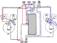
Here is the photo of the wiring cleaned up, simplified to just speaker stuff, and the wires marked BLU & RED were made so, WHT is black.
I do not think the horn is a piezo, it looks like the magnet on a BIC horn but with a different horn. Need a better picture.
dave
Attachments
If the horn tweeter was 16 ohm and in parallel with the 16 ohm mid then the XO point would, indeed, be 600Hz. Could the horn tweeter take that?unless i'm missing something with the supplied schematic both mid and tweeter are paralleled and with the 33mfd cap it's a 600hz x-over.
if you trace it out you can have both internal and external speakers running at the same time the switching ensures that it's in series.
Thanks for the external speaker switching information, tracing out the wiring proved a problem for me!
You've gone to a lot of trouble there, Dave, and for purely academic reasons - a true investigator!
I'll have a good look at your wiring interpretation.
See what you've started Mike - any chance of more detailed images of the horn tweeter or have you lost the will to live? 😀
I'll have a good look at your wiring interpretation.
See what you've started Mike - any chance of more detailed images of the horn tweeter or have you lost the will to live? 😀
Here are more pics of the horn. I “did” have a multimeter but it was lost along with most of my electronics test/repair tools in a recent move (I suspect my stepson lol). Gives me a reason to pick up another one tomorrow. I am enjoying the lessons and looking up things to better understand what you are all talking about.
Attachments


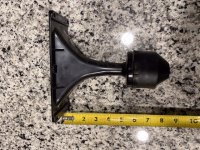
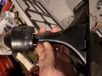
I ws going to ask more pictures of the *weird* horn driver.
Thanks.
It is WAY too tall either for a Piezo disk or a Ceramic Magnet BUT some smallish Alnicos were built with actual magnet rod inside a stamped iron cup ... quite common in one era for small portable radio speakers.
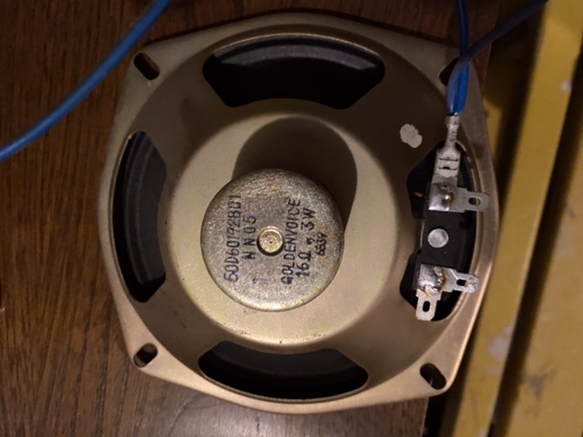
And notice what does the midrange unit use:
"the shadow speaks".
Similar era alnico speaker (Elac):

Note: a few tweeters, both cone and drivers, *included* series capacitor straight from factory, a few inside a "hood", all to ease non Tech people installatio0n: "just connect it in parallel with current speaker"
I find it intriguing that besides the way too tall housing, there is a sticker stating "3.9" .... "3.9uF inside?"
Thanks.
It is WAY too tall either for a Piezo disk or a Ceramic Magnet BUT some smallish Alnicos were built with actual magnet rod inside a stamped iron cup ... quite common in one era for small portable radio speakers.
And notice what does the midrange unit use:
"the shadow speaks".
Similar era alnico speaker (Elac):
Note: a few tweeters, both cone and drivers, *included* series capacitor straight from factory, a few inside a "hood", all to ease non Tech people installatio0n: "just connect it in parallel with current speaker"
I find it intriguing that besides the way too tall housing, there is a sticker stating "3.9" .... "3.9uF inside?"
Last edited:
I found this image of a 'vintage alnico 3" x 7" horn tweeter".Note: a few tweeters . . . *included* series capacitor straight from factory, a few inside a "hood" . . . the way too tall housing
An externally hosted image should be here but it was not working when we last tested it.
It doesn't have a 'hood' or 'tall housing' which supports your hypothesis that Mike's tweeter may, indeed, contain the necessary high pass capacitor.
Attachments

- Home
- Loudspeakers
- Multi-Way
- Help with console speaker renovation