Hi guys. I've been busy with other things so not been bothering anyone around here lately...
But I have another work related question:
We have some old (50-60 years old) equipment which uses Allied Control open relays (contactors essentially) for the control logic- turning on and off etc. The main one is going bad (or is already bad) in a couple consoles.
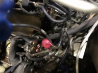
I have three 'tested good' contactors I farmed out of a donor, but when comparing to a "good/working" console, I notice what I had originally thought might be a arc suppressing capacitor, but now I'm not sure what it is exactly. (shown as "D3" on paperwork)
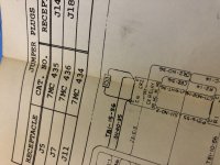
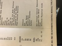
Checking the ancient scrolls for schematics/wiring/build diagrams, the part in question is listed as "Selenium Thyrector Diode" No value listed. (pic 3&4)
The part itself has "1501" (I think) on the top line and "GEV1" on the bottom line. (pic 1&2) My google-fu has proven to be found wanting... Note this is the "newer" console (from 1978 I think) and what is most interesting is that this component, though shown on the wiring diagram, is not listed in the parts. The older diagram (early-mid 60's) calls it out, but no value as noted above. (pic 4)
I know you guys know more about this stuff than I ever will, so any ideas on a direct, or current production replacement, for this little guy? It does not seem to have any polarity, and is on the 110VAC line of the main contactor. Is it critical to proper operation of the contactor?
(I want to pre-set these contactors so the maintenance tech can "drop" them in, without dealing with any soldering or other stuff. I'll number marker the wires and he can just crimp connect them in to the correct numbered wires.)
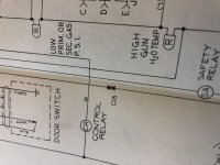
Looking at the schematic, the symbol is drawn like two diodes butting into one another: ->|<- with one side going to the "hot" contact and the other going to the "neutral" contact. (pic 5) Both contacts are on the same contactor, powered by a shared coil, which gets power prior to this component- the component is on the open side of the contacts, bridging hot and neutral. So, it has no effect on the coil itself as far as I can tell.
1) what was the intent of this?
2) what is a currently available replacement I can spec in? (contacts are rated six amps max)
Thank you guys for reading, and hopefully pointing me in the right direction!
But I have another work related question:
We have some old (50-60 years old) equipment which uses Allied Control open relays (contactors essentially) for the control logic- turning on and off etc. The main one is going bad (or is already bad) in a couple consoles.
I have three 'tested good' contactors I farmed out of a donor, but when comparing to a "good/working" console, I notice what I had originally thought might be a arc suppressing capacitor, but now I'm not sure what it is exactly. (shown as "D3" on paperwork)
Checking the ancient scrolls for schematics/wiring/build diagrams, the part in question is listed as "Selenium Thyrector Diode" No value listed. (pic 3&4)
The part itself has "1501" (I think) on the top line and "GEV1" on the bottom line. (pic 1&2) My google-fu has proven to be found wanting... Note this is the "newer" console (from 1978 I think) and what is most interesting is that this component, though shown on the wiring diagram, is not listed in the parts. The older diagram (early-mid 60's) calls it out, but no value as noted above. (pic 4)
I know you guys know more about this stuff than I ever will, so any ideas on a direct, or current production replacement, for this little guy? It does not seem to have any polarity, and is on the 110VAC line of the main contactor. Is it critical to proper operation of the contactor?
(I want to pre-set these contactors so the maintenance tech can "drop" them in, without dealing with any soldering or other stuff. I'll number marker the wires and he can just crimp connect them in to the correct numbered wires.)
Looking at the schematic, the symbol is drawn like two diodes butting into one another: ->|<- with one side going to the "hot" contact and the other going to the "neutral" contact. (pic 5) Both contacts are on the same contactor, powered by a shared coil, which gets power prior to this component- the component is on the open side of the contacts, bridging hot and neutral. So, it has no effect on the coil itself as far as I can tell.
1) what was the intent of this?
2) what is a currently available replacement I can spec in? (contacts are rated six amps max)
Thank you guys for reading, and hopefully pointing me in the right direction!
Attachments

Hi,
That it is a varistor. They use for suppressors to protect devices and circuits from transient abnormal voltages including an ESD (electrostatic discharge) and a lightning surge.
That it is a varistor. They use for suppressors to protect devices and circuits from transient abnormal voltages including an ESD (electrostatic discharge) and a lightning surge.
Well, the gun operates at 40 kW DC nominally... Actually, the ignition pulse- that's an ignition spark gap at ~150 VAC open circuit... Would that interference cause the coil to drop out? no, the coil is not under the "protection" of this.
So, what would be a currently available replacement for such a gizmo? I need to order a dozen or so to have on hand. I'd rather not go hunting down surplus stuff (I'm already doing that for more contactors)
So, what would be a currently available replacement for such a gizmo? I need to order a dozen or so to have on hand. I'd rather not go hunting down surplus stuff (I'm already doing that for more contactors)
Hi,
Also it can be a TVS. Attached a link to LITTLEFUSE company that sell both and has literature explaining about both devices. I am incline that it is TVS since in the drawing show it as two diode back to back.
Varistor | Metal Oxide Varistor - Littelfuse
Also it can be a TVS. Attached a link to LITTLEFUSE company that sell both and has literature explaining about both devices. I am incline that it is TVS since in the drawing show it as two diode back to back.
Varistor | Metal Oxide Varistor - Littelfuse
AAAAAAAhhhhhh!
Transient-voltage-suppression diode - Wikipedia.
I found the right "thing"; however how do I specify the exact component I need, so I can source them?
It lists "arcing" such as from a motor- the ignition pulse for the plasma gun uses a spark gap. THIS is what it's there.
Still need to know what to source...
Hi,
If you look at your picture it is look like a varistor since the color it is red. If you look at the LITTLEFUSE picture for the TVS it looked like a diode. So maybe somebody changed it with a varistor since it is color red. One thing that you can do since it is connected to the relay coil is read the voltage at the coil and then you can determine which one to buy. Normally I used 50 volt higher than the working voltage.
If you look at your picture it is look like a varistor since the color it is red. If you look at the LITTLEFUSE picture for the TVS it looked like a diode. So maybe somebody changed it with a varistor since it is color red. One thing that you can do since it is connected to the relay coil is read the voltage at the coil and then you can determine which one to buy. Normally I used 50 volt higher than the working voltage.
On the Wikipedia link, it shows the TVS with the same schematic diagram as shown on the original (and later version) schematic.
But the later version does not call out the part, even though it is shown on the schematic, and clearly in place.
Since there is the high frequency AC spark ignition signal riding on the DC power cables to the gun for ignition, that high voltage output could easily damage stuff (it wreaks havoc with the robots if the cable is in Contact with the arm), so I think that is the right part.
And it’s not across the coil, the coil pulls in the hot on one contact and the neutral on the other contact. The contact outputs are connected with this component.
Coil is 110/120 vac. Contacts are rated for 6A.
Is there a fundamental difference between the TVS and Thyrector (not varistor- unless these are different names for the same thing?)
Hi,
In the schematic do not showed how they energize the relay. Can you find out in the schematic how they do it. Do they use another relay to energize this one or they are using a semiconductor like a TRAIC or an SCR. Also found a link where they explain how to select the right varistor.
Select the Right Varistors for Overvoltage Circuit Protection | Electronic Design
Last edited:
Nothing that fancy.
A push-button (NO) energizes the coil which back-feeds through a NC switch, which, when pressed de-energizes the coil so it opens the contacts.
Fail-safe if power is lost to the console all stops.
A push-button (NO) energizes the coil which back-feeds through a NC switch, which, when pressed de-energizes the coil so it opens the contacts.
Fail-safe if power is lost to the console all stops.
Hi,
Okay then I think that the varistor it is the right one. Also found a link where they explain how to select the right varistor.They said use 20% more from the working voltage.
Select the Right Varistors for Overvoltage Circuit Protection | Electronic Design
Okay then I think that the varistor it is the right one. Also found a link where they explain how to select the right varistor.They said use 20% more from the working voltage.
Select the Right Varistors for Overvoltage Circuit Protection | Electronic Design
Hi,
Link to the LITTLEFUSE varistor series. I think the right one for you application is the part number V140LA10AP.
http://www.farnell.com/datasheets/2608835.pdf
Link to the LITTLEFUSE varistor series. I think the right one for you application is the part number V140LA10AP.
http://www.farnell.com/datasheets/2608835.pdf
That’s a great help, thank you.
I’ll dig into it and get some ordered so I can pre-prep these contractors for the maintenance tech.
I’ll dig into it and get some ordered so I can pre-prep these contractors for the maintenance tech.
Thanks for that. I’ll spec 150v then.
And these consoles, though built to survive nuclear attack, have had all manner of abuse in their 50+ years. Not to mention hacked up wiring “just to get going” when something does fail, which remains for years...
And these consoles, though built to survive nuclear attack, have had all manner of abuse in their 50+ years. Not to mention hacked up wiring “just to get going” when something does fail, which remains for years...
Looking at the data sheet, I see this "branding" on one of the 150V ones: P1501
I think the original part had "1501" on the top line... Seems reasonable?
I think the original part had "1501" on the top line... Seems reasonable?
- Home
- Design & Build
- Parts
- HELP! With Component Identification