I am developing a Class D amplifier as a senior project in college, which hopefully will help me get a job designing amplifiers. This is my first experience designing a switching amplifier, although I have repaired a few. I deced to use a IC amplifier to ease the design of the PWM stage, and hang my own gate drivers from the IC. It all works fine in my prototype amplifier but I have not tried with any high voltage supplies yet.
I have been reading all the posts in this forum and trying to wrap my mind around all the wonderful information in here. My question about my amp centers around the feedback - namely that I have none. Is there any need to add feedback for proper operation of the amplifier? Or can I test without feedback initially and add it later to improve operation?
Because of a conversation with an IR tech it appears that the undervoltage lockout will keep the gate signal low when the logic supply drops, which eliminates the need to actively sense when the HV rail drops during shutoff. That was a concern but if I am corrent then there is no problem. [?]
The PCB will arrive Tues and I will being soldering components then. I am using IRF6665 FETs which are in a SMT package.
Also, I am having a hard time determining the proper values of the RCD clamp on the power supply primary. It seems to me that the R and C values are chosen to allow somepower to be dissipated during switching where the zener would overheat with them. Are there calculations to determine a proper value for these components, or else what should I look for in my simulations when adjusting values?
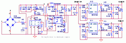
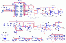
The amplifier schematic is attatched below. I will post the power supply as well. I can also post the PCB files.
Evan
I have been reading all the posts in this forum and trying to wrap my mind around all the wonderful information in here. My question about my amp centers around the feedback - namely that I have none. Is there any need to add feedback for proper operation of the amplifier? Or can I test without feedback initially and add it later to improve operation?
Because of a conversation with an IR tech it appears that the undervoltage lockout will keep the gate signal low when the logic supply drops, which eliminates the need to actively sense when the HV rail drops during shutoff. That was a concern but if I am corrent then there is no problem. [?]
The PCB will arrive Tues and I will being soldering components then. I am using IRF6665 FETs which are in a SMT package.
Also, I am having a hard time determining the proper values of the RCD clamp on the power supply primary. It seems to me that the R and C values are chosen to allow somepower to be dissipated during switching where the zener would overheat with them. Are there calculations to determine a proper value for these components, or else what should I look for in my simulations when adjusting values?
The amplifier schematic is attatched below. I will post the power supply as well. I can also post the PCB files.
Evan
Attachments
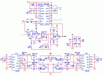
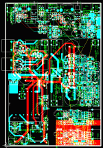
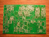
Here is the PCB. The input section is at the top, the power supply along the left side, and the amplifier is in the middle right. At the bottom right I placed 2 USB DACs using the PCM2702 because I had extra room and if these work well I will design one into my computer speakers.
The grounding isn't quite where it should be on the amplifier and input [power mixes into signal ground in some places] but I had to send them in by a certain time. Also, some of the ground planes did not show up on the amplifier and input sections.
Thank you for any comments or suggestions!
The grounding isn't quite where it should be on the amplifier and input [power mixes into signal ground in some places] but I had to send them in by a certain time. Also, some of the ground planes did not show up on the amplifier and input sections.
Thank you for any comments or suggestions!
Attachments
toooooo complicated.
You are mixing too much things together, it's hard to debug. Especially the difficult and dangerous high voltage SMPS--It may cost you your life. There's some safty guide in the tube forum.
Maybe design a single amplifier first ; debug it with DC power supply and signal source; bulid the PSU and ADC later; and finally integrate them together would be better.
Also,the 5V and 12V power supply need not to use switching regulator, a cheap linear one will work well.
Trangular wave modulator can work without feedback, you can open-loop test it. But for practical use, feedback is always needed for low output resistance & low distortion.
Tell you a good news -- I haven't build ANY class-D amplifier before. And I would probably build NONE in the following 2 years -- I have too many things to do in my CFD studies.
//hehe.
//hehe.
Kenshin, thank you for your concern 🙂 I worked at an audio company with a similar power supply before so I am confortable with using it, I just didn't get in on the design part, just testing. I chose the switchers because it added some required complexity, I had magentics for it, and it was rather simple. The 5V regulator only produces 112mVpp ripple while supplying 2.2A, and the 12V is nearly as good. Those are already working well.
I contacted IR's local distributor about sampling parts and they were happy to supply me with samples 🙂 As a student I don't feel bad about sampling parts, especially when the distributor was so wonderful about it, and I can compensate IR with business later.
The amplifier feedback concerns me beause the MAX4295 has an error amplifier in it, with the output pin exposed. I believe I should be able to use that to add feedback just like a discrete modulator. I thought perhaps I could get some ideas to try before the PCBs came in.
I have some good linear supplies that I can use while testing the amplifier, and loads to test the PSU so I am not integrating everything right away. Thanks for the idea tho!
local distributer... so I can't get any free samples directly from IR?
BTW: you are using many expensive MAXIM ICs.
the system may became too expensive for commercial use.
may be you could try a self-osc one like SODA.
the ICs involved are only comparator + gate driver.
BTW: you are using many expensive MAXIM ICs.
the system may became too expensive for commercial use.
may be you could try a self-osc one like SODA.
the ICs involved are only comparator + gate driver.
Hmm, interesting idea. I layed out a board based on a much simpler design but I sampled or got from the university all the expensive stuff so it cost me very little. You are right.
IR has lots of distributors, I just checked their website to find my local rep. Go ahead and give it a shot if you're interested in parts.
PCB rev1 came in today. There are some errors, but nothing keeping this board from being useable. Hopefully I won't have to make another rev.
Sorry about the photo quality. My 2.0MP Olympus is getting a bit old.
Attachments
- Status
- Not open for further replies.
- Home
- Amplifiers
- Class D
- help with class D amp and SMPS