Hi,
Need some advice once again........ 🙂
I am using this power amp for a project,
the problem is if I connect it to a normal line level input it is to powerful for the amp. I think the amp must originally designed up to take a very low level input.
Can any one advise me on the best way to adjust this amp to be able to handle a normal line level? I know if I do it wrong I will end up with loss of sound quality and bass,
it is probably needs the input to be at least as half as sensitive as it is allready
thanks
Attachments

Last edited:
,
The gain appears to be 43.5dB, which is high for a power amplifier.
An easy way is to add a series resistor before each input 100k resistor.
The input voltage will be halved (-6dB) if the series value is 40.5k.
This will actually extend both the bass and highs a little
because of the input filtering capacitors.
Or, you could add a 10k stereo volume control at the input, and adjust it however you like.
http://www.ebay.com/itm/DACT-Type-S...volume-control-pot-D-Shape-Shaft/192127131789
probably needs the input to be at least as half as sensitive as it is.
The gain appears to be 43.5dB, which is high for a power amplifier.
An easy way is to add a series resistor before each input 100k resistor.
The input voltage will be halved (-6dB) if the series value is 40.5k.
This will actually extend both the bass and highs a little
because of the input filtering capacitors.
Or, you could add a 10k stereo volume control at the input, and adjust it however you like.
http://www.ebay.com/itm/DACT-Type-S...volume-control-pot-D-Shape-Shaft/192127131789
Last edited:
What is your present max. line level input and does it not already have a volume control? If it still needs more attenuation, when you say "at least half as sensitive" and you are talking in terms of perceived volume, the actual attention would be logarithmic and the voltage reduction would need to only a small fraction of the line level. That seems inappropriate for a peak line level of nominally only 1V.
Read this very useful article about it at ESP (Rod Elliott's site.) for guidance on values and explanation. Voltage Dividers and Attenuators
Read this very useful article about it at ESP (Rod Elliott's site.) for guidance on values and explanation. Voltage Dividers and Attenuators
Yes.
As-is gain is around 115X , it can put out some 17V RMS tops, so sensitivity is around 17/115=150mV ; quite sensitive compared to common pre out/pwr amp in levels, which usually hover between 300mV and 1V .
Do not mess with NFB values so next best is to apply some attenuation, as suggested above.
If not enough, you can , say, double input series resistor even higher, say 220k
Doubt you need more than that.
Can any one advise me on the best way to adjust this amp to be able to handle a normal line level?
That is what volume control is used for, a log pot of your choosing, it is an adjustable resistor divider if you will... It reduces the signal level without influencing the bandwidth.
,
The gain appears to be 43.5dB, which is high for a power amplifier.
An easy way is to add a series resistor before each input 100k resistor.
The input voltage will be halved (-6dB) if the series value is 40.5k.
This will actually extend both the bass and highs a little
because of the input filtering capacitors.
Or, you could add a 10k stereo volume control at the input, and adjust it however you like.
DACT Type SMD Stepped Attenuator 21 step volume control pot D Shape Shaft | eBay
I think adding a series resistor would attenuate the highs (severely) because of the effect of the 1nF cap in parallel with the 100k and 68k. Even a 6k8 (which would give no real attenuation) would be around 3db down at 20kHz.
thanks i will have a read through that.What is your present max. line level input and does it not already have a volume control? If it still needs more attenuation, when you say "at least half as sensitive" and you are talking in terms of perceived volume, the actual attention would be logarithmic and the voltage reduction would need to only a small fraction of the line level. That seems inappropriate for a peak line level of nominally only 1V.
Read this very useful article about it at ESP (Rod Elliott's site.) for guidance on values and explanation. Voltage Dividers and Attenuators
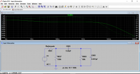
The important thing to get right with this is the effect of C805.
The original design would be fed from a known impedance and that will determine the effect of the capacitor action, in other words the high frequency roll off. We really need to know what you will be feeding this power amp from in order to make an informed judgement.
The original design would be fed from a known impedance and that will determine the effect of the capacitor action, in other words the high frequency roll off. We really need to know what you will be feeding this power amp from in order to make an informed judgement.
Thanks for advice, I was using the volume on the input to the pre to drop my signal and it was ending up with a pretty weak sound, will try adding a volume between the pre and power amp, cheers
thanks for the link i didnt know they made stepped so small with smd's,
The gain appears to be 43.5dB, which is high for a power amplifier.
An easy way is to add a series resistor before each input 100k resistor.
The input voltage will be halved (-6dB) if the series value is 40.5k.
This will actually extend both the bass and highs a little
because of the input filtering capacitors.
Or, you could add a 10k stereo volume control at the input, and adjust it however you like.
DACT Type SMD Stepped Attenuator 21 step volume control pot D Shape Shaft | eBay
Last edited:
Have a look at post5.
That little two element circuit will attenuate the input.
I consider the values adopted to be too high.
I suggest you replace the 68k with a 10k and replace the 4k7 with a 1k. (~-20dB)
If that is still too loud, then add a second 1k across the first. This gives an effective 500r for ~-26dB.
You still have the option to add another (third) resistor across the 500r. adding a 330r gets the attenuation to ~-34dB
Thanks for advice, I was using the volume on the input to the pre to drop my signal and it was ending up with a pretty weak sound, will try adding a volume between the pre and power amp, cheers
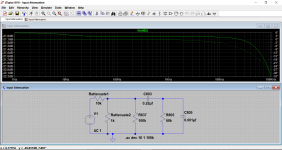
It is really the output impedance of the stage you are driving the power with that is the important thing.
This shows the response of the two suggestions so far, Andrews is the second one. All these assume a low driving impedance.
I've attached the sim file so that anyone can have a play and see the effect of any changes.
Attachments
If reducing the 1nF capacitor is not an option ( i do not know if that is so or not ), that maybe you could use a noninverting opamp repeater, thus driving the power amp from a stiff enough impedance so as to not alter the upper bandwidth, and also at the imput of the repeater you could set whatever impedance divider you want, making it much simpler to choose.
Do not mess with NFB values so next best is to apply some attenuation, as suggested above.
Why not?
Because you could mess with negative feedback loop's stability, and you do not want that.
That high CLG may be there for a reason.
The safest way is to reduce the imput signal.
The easiest way to do that is with a potentiometer at the power amp imput, but as it has been pointed out, the upper bandwidth could suffer, so you could try as i have said, using opamp repeaters, TL072 is very cheap, with good enough performance, it's is safe for unity gain, and is has very high imput impedance.
You can alter the NFB but it is not always straightforward. At the very least you would need to use a scope and investigate the stability margins. There is a technique you can use to increase the feedback while maintaining stability but that too needs careful implementation.
The circuit in original form really needs to be fed from something having around 2k output impedance.
The circuit in original form really needs to be fed from something having around 2k output impedance.
I'd still be tempted to try it 😉
The stability issue is not to be taken for granted, believe me 🙂
Unless you could test it with the proper gear, or simulate it exactly as it is in any aspect, then, i'd suggest that you leave it as it is, and work at it's imput.
Granted, I'd use a scope to test for oscillation, I'd take the gain to say 30dB without too much concern, but that's just me I guess.....😱
Last edited:
- Status
- Not open for further replies.
- Home
- Amplifiers
- Solid State
- help with changing input sensitivity please