Could someone please show me maybe a diagram of using the center tap of the filament transformer. I know that you can take the cathode bias resistor to the center tap and not use a hum pot. I heard of using two maybe 1.25 ohm mills resistors. Do they go from the cathode resistor to the filaments? Also, Do you reference the grid to the center tap then? Any help would be greatly appreciated. Thanks!
Kennyg
Kennyg
You need to understand that this is my first amp build. I am familiar with electronics, but new to tubes. Normally the cathode bias resistor is referenced to ground, and also the grid is referenced to ground. When you take your bias resistor to the center tap, Do you reference the grid to the center tap? With the same resistor that would normally go to ground.
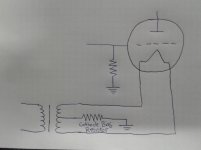
I didn't understand till I drawn it out. Is this the correct way...?
Keep re-re-drawing until it makes sense at a glance.
While the filament winding is "over there" at the PT, for purposes of the triode we need only see it bridging the filament and presenting a CT which is equivalent to a uni-potential cathode.
Many readers find it helps focus to draw grounds all on a level (like me today laying-out a garage slab at Ground LEVEL).
Attachments
Keep re-re-drawing until it makes sense at a glance.
While the filament winding is "over there" at the PT, for purposes of the triode we need only see it bridging the filament and presenting a CT which is equivalent to a uni-potential cathode.
Many readers find it helps focus to draw grounds all on a level (like me today laying-out a garage slab at Ground LEVEL).
Thanks for that aspect. I understand it totally. I was a building contractor for 35 years.
Kennyg
There is no reason why you cannot take the centre tap as the cathode return point as it is balanced so no need for a hum pot or a pair of resistors.
I'd try it without the 'hum pot' first. If acceptable, I'd use a pair of 10R resistors and form a faux CT for the biasing network. The winding will have an impedance which varies with frequency, the resistors will not.
If not acceptable, ~20R pot across the winding with wiper to the bias network, and a pair of 4R7 resistors from each end of the pot to wiper.
And yes, reference the grid to signal common, via a resistor, as you have drawn.
KG_ if you had to restart as of today, would you go your own way or the employed route?. Not a simple question, I know.. and things are changing here too, very much like they were in '07 over your way.
Hanze.
Last edited:
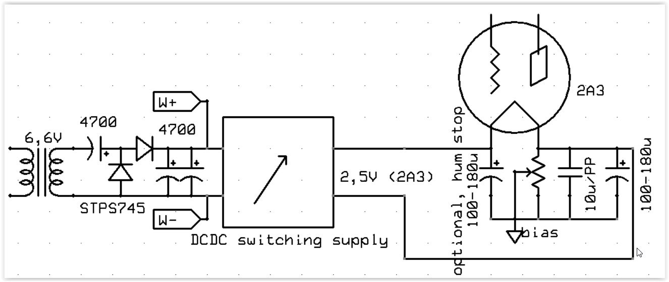
if you do not have luxury of exact 2,5v wirings. (i should do humdinger pot, but is just fine now)
DC-DC Buck Step-down Regulator Converter 4.2~23v to 3V 3.3V 5V 9V 12V 24V Module 699930621128 | eBay

hpeter, did you try this out? Its.... so cheap!  but its a switching supply (like all these nasty 5V cellphone chargers) ..... it regulates the voltage by switching between low dissipation, on and off modes.
It would be worth trying out since it is so darn cheap ... But if you tried it and know it makes noise then I would personally skip it and build a linear power supply.
Or stick to a decent quality 2.5V transformer that has a center tap. Hanze noted the change in impedance with frequency, but this is really not so significant since the impedance is already very small, and the dominant frequency comes from the mains anyway...
but its a switching supply (like all these nasty 5V cellphone chargers) ..... it regulates the voltage by switching between low dissipation, on and off modes.It would be worth trying out since it is so darn cheap
... But if you tried it and know it makes noise then I would personally skip it and build a linear power supply.Or stick to a decent quality 2.5V transformer that has a center tap. Hanze noted the change in impedance with frequency, but this is really not so significant since the impedance is already very small, and the dominant frequency comes from the mains anyway...
Last edited:
i use it long time in my stax amp, i have low speed fan aimed at modules (low flow), coils are a bit warm
linear supply would be much hotter, with requirement of alu heatsinks.
actually a sepic type converter (not this one), can work with lower or higher input.. you always get required output voltage.
try that with linears
with hundreds of khz switching i do not worry about bad sound, no batman here...
modded the modules with some tantalum and foil caps at output... just to be safe
it was convenient solution , because lundahl 6,6~ windings, he makes no xformers with 2,5~
"switching nastiness" you can fix by adding some coils and caps /LC filters/ if you are worried that much.

funny story- i could see some of the almost 1mhz switching on secondary windings going to stax. (before mods)
probably 2a3 cathode amplified the tiny ripple of dc supplies and sent it to opt...
since opt centertap is grounded, i do not think transfer of this freq is made by capacitance between windings.
maybe lundahls have the bandwidth
linear supply would be much hotter, with requirement of alu heatsinks.
actually a sepic type converter (not this one), can work with lower or higher input.. you always get required output voltage.
try that with linears
with hundreds of khz switching i do not worry about bad sound, no batman here...
modded the modules with some tantalum and foil caps at output... just to be safe
it was convenient solution , because lundahl 6,6~ windings, he makes no xformers with 2,5~
"switching nastiness" you can fix by adding some coils and caps /LC filters/ if you are worried that much.
funny story- i could see some of the almost 1mhz switching on secondary windings going to stax. (before mods)
probably 2a3 cathode amplified the tiny ripple of dc supplies and sent it to opt...
since opt centertap is grounded, i do not think transfer of this freq is made by capacitance between windings.
maybe lundahls have the bandwidth
Last edited:
Hi hpeter
I found this one:

https://www.ebay.com/itm/DC-DC-Buck...V-5A-Converter-Voltage-Regulator/272834659085
It cost a little bit more, but I figure it might be worth it. I hope to try it out soon.
Ian
I found this one:
https://www.ebay.com/itm/DC-DC-Buck...V-5A-Converter-Voltage-Regulator/272834659085
It cost a little bit more, but I figure it might be worth it. I hope to try it out soon.
Ian
LM2576 ? has 56khz
The listing says Operating Frequency: 180kHz however I did not check the chipset.
Guess it makes sense to question the seller before you buy...
- Status
- This old topic is closed. If you want to reopen this topic, contact a moderator using the "Report Post" button.
- Home
- Amplifiers
- Tubes / Valves
- Help with Cathode biasing of a 2A3 using CT of filament transformer