Hi Guys (and Gals),
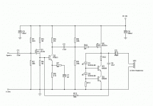
I usually just lurk around this forum and try to learn what I can But I have run into a problem. I've cobbled together a design based on at least two other designs trying to make a good class A headphone amp. I could post this at Headwize but I don't have image hosting so it's easier to post it here. I'm currently taking electronics classes at a local college at night but I'm not that far advanced. I don't think that what's confusing me will be any problem for many of you so don't snicker. I'll get there eventually. Hopefully the schematic is below this post and ledgible. The problem I'm having is biasing the CCS. I believe that R11 should be 1K but I'm not so sure about the value of R12. I think 30 ohms but I'm not at all comfortable guessing. Can anyone give me a hand?
G
Attachments
It's kind of an oddball current source, if you ask me. I would have though R12 should be at the emitter of Q4, R11 should be where D1 is, and D1 where R11 is. That's the canonical example of a cascoded constant current source, anyway.
To set R12, find the voltage drop across D1, subtract the Vbe of Q4, and divide by the desired current. Out of the blue sky, I would guess 30Ω will give you about 40mA.
The Art of Electronics by Horowitz and Hill has an extensive treatment of constant current sources, and it is possible to learn everything about this circuit from that book.
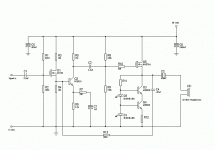
You mean it should look like this? The ccs was used on the anode of a tube gain stage. I changed the Pchannels to Nchannels and put it on the source of the BUZ72A just the way it was. Thanks for correcting me. That's one more thing that I have learned. I will get the book also. Thanks.
Attachments
Ah! Much better. As it was in the first schematic, the CCS would not work at all.
Now, in the second schematic, you have the forward voltage of LED D1 minus the Vbe voltage of roughly 0.67V of Q4. This will be approximately the voltage across R12. Apply ohm's law, and you've got your current. R11 is there to bias the LED's at the correct current, and to supply base current to Q3 and Q4. You'll want to set this so that about 10 or 20mA flows through the LEDs. Also, R11 will provide a more stable bias current for these LEDs if it is tied to the positive supply rail instead of the output, but that may require a higher power-rated part... might be an issue if you're trying to build this circuit with parts on hand...
good luck,
- Status
- Not open for further replies.

