Hi all
I know this should be pretty basic but I cant seem to make out where to connect the probes when adjusting bias. Can someone please give me some guidance? 😱
Here are the instructions, diagram and some photos of the circuit.
From what I can tell one probe has to be connected to R12 but where exactly do I connect the other one to? 😕
An externally hosted image should be here but it was not working when we last tested it.
An externally hosted image should be here but it was not working when we last tested it.
An externally hosted image should be here but it was not working when we last tested it.
An externally hosted image should be here but it was not working when we last tested it.
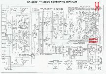
You need to measure the voltage drop over R23 (left channel) and R24 (right channel). Both resistors are located outside the PCB. As far as I see on the schematic, they are 0.5R - that means, you have to set 15mV across them - in this case the quiescent current is 30mA, as recommended by the manufacturer.
Red arrows show where DMM leads have to be connected.
Red arrows show where DMM leads have to be connected.
Attachments
You need to measure the voltage drop over R23 (left channel) and R24 (right channel). Both resistors are located outside the PCB. As far as I see on the schematic, they are 0.5R - that means, you have to set 15mV across them - in this case the quiescent current is 30mA, as recommended by the manufacturer.
Red arrows show where DMM leads have to be connected.
Thank you!
- Status
- Not open for further replies.