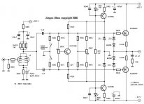
Hi guys, I need some help with a hybrid amplifier I have built. You can see the schematic below.
The problem is that it slowly gets hotter and hotter while playing (regardless of volume), it takes about 10 min for it to reach a temprature were I cant touch the case of the output transistors (IRF540/9540). The transistors do have very good thermal conduction with the heatsink. The bias is only 0.23amps, and I am using 4 ohm speakers. The temprature of the transistors keeps increasing regardless of it playing or not.
I know it seems like I need a bigger heatsink but I doubt that is the problem. A zobel network does not help either. I think I just have a thermal runaway problem, but I could be wrong.
I was wondering if placing the 2sc2240 transistor on the main heatsink would help stabilize the temprature. If not what else can I do?
Thanks
Lawrence
Attachments
Placing the 2SC2240 to the heatsink, probably helps. If no, put it to the case of the output device directly, or increase the source resistors to 0.33R, or 0.47R.
The original design use BUZ900/905 pair which are lateral mosfets, with negative TK, over 100mA. The IRF540/9540 pair is vertical mosfet which has positive TK up to few ampers. This results the thermal runaway, You found.
sajti
The original design use BUZ900/905 pair which are lateral mosfets, with negative TK, over 100mA. The IRF540/9540 pair is vertical mosfet which has positive TK up to few ampers. This results the thermal runaway, You found.
sajti
lawbadman said:
I was wondering if placing the 2sc2240 transistor on the main heatsink would help stabilize the temprature. If not what else can I do?
Thanks
Lawrence
Hi Lawrence
The answer of Sajti is absolutely correct...and i only want to add a small point..
Check if the off set at the output terminal is the some when the amp become hot...as if you trimm the off set in cold conditions...after warm up maybe it change a litlle ..and this can provoke some increment the output mosfets idle disipation...
I'd throw in a 0.1uf metallized popypropylene cap on each rail as close to the output devices as possible. Also, get the BUZ parts or,
a) Increase the source followers to 0R47 that can but I'm not sure it will help.
b) Replace the output devices with 2sk1058 & 2sj162 (lateral mosfets but cheaper than the BUZ parts) keep the 0R47 source followers if so.
c) add a series coil (10 turns of 1.5mm enameled copper on a crayon//damped with 8R) at the output.
using a larger emitter resistor will help but not much. the problem with irf mosfets is that they need a lot of swings at gate to drive. As such, a 0.47ohm resistor isn't going to do a lot of good vs. a 0.22ohm.
using a thermally coupled vbe multiplier is the way to go. better yet, use a "complementory" Vbe multiplier, like the ones in JC3: essentially a npn vbe multiplier for the n-channel and a pnp vbe multiplier for the p-channel output device. and mount them on top of their respective output transistors.
Otherwise, go back to the lateral mosfets.
Would using a biased mosfet as a bias setter and temperature compensator instead of an amplified diode transistor help?
I would try using the amplified gate threshold of a mosfet for the bias control and the temperature compensation, possibly either an IRF540 or IRF9540, mounted on the heatsink or on the tab of one of the output mosfets.
230mA of idle current is 20W at ±42V
How much sink do you have?
A 2*C sink is about 2" X 3" X 4", that would give you a 40*C rise above ambient.
I have measured a glass front audio rack with just such an amplifier having an internal ambient of 55*C with the room ambient at 25*C.
Under those conditions the outputs will be over 100*C, the boiling point of water.
Hi Guys, Thanks for the replies.
I will change the mosfets to the BUZ900P/905P or 2sk1058 & 2sj162. Anyone know were on the internet I can buy the BUZ900P/905P mosfets?
I have a few BUZ901CDP and BUZ906DP double die L mosfets, can they be used?
Thanks
Lawrence
I will change the mosfets to the BUZ900P/905P or 2sk1058 & 2sj162. Anyone know were on the internet I can buy the BUZ900P/905P mosfets?
I have a few BUZ901CDP and BUZ906DP double die L mosfets, can they be used?
Thanks
Lawrence
BUZ901CDP and BUZ906DP - Yep, they'll fit & you can increase the rails safely for more power (if you want and the heatsinking is adequate). Keep the .22 followers in this case and bias them to ~100mA per device.
Are the output devices connected with wires to the PCB? You'd want those as short & thick as possible to avoid problems.
Are the output devices connected with wires to the PCB? You'd want those as short & thick as possible to avoid problems.
Thanks for the reply lucpes.
Tell me something, how do you know that the BUZ901CDP and BUZ906DP will work, is there some sort of characteristic of the mosfets that you use or what?
Lawrence
Tell me something, how do you know that the BUZ901CDP and BUZ906DP will work, is there some sort of characteristic of the mosfets that you use or what?
Lawrence
The Magnatec lateral mosfets' characteristics (buz90x) are very similar throughout the range of their products, you can swap them around with no problems (lowish current/voltage parts with higher rated ones). One advantage of using l-mosfets is that they do not require temperature compensated bias because of their negative TK over 100ma.
The schematic you presented in the first post in the thread uses l-mosfets and does not include a unnecesary 'proper' biasing part (temperature compensated) that would allow you to use vertical mosfets (what you're using now, without temp comp, resulting in thermal runaway). You can modify the circuit to do that but why bother?
The schematic you presented in the first post in the thread uses l-mosfets and does not include a unnecesary 'proper' biasing part (temperature compensated) that would allow you to use vertical mosfets (what you're using now, without temp comp, resulting in thermal runaway). You can modify the circuit to do that but why bother?
My proposal has two steps:
First: put the 2sc2240 to the same heat sink as the power Mos.
Second: exchange the red leds by 3 standard diodes (i.e. 1N4148).
Put this diodes also on the heat sink. Increase the 240 Ohms resistors to 330 ohms in order to get back similar currents as in original through the drivers.
May be these points are sufficient.
Did you measure your idle current also during running hot?
Which values do you get?
Good luck
Markus
Trouble
Hey Guys
I put in the BUZ901CDP and BUZ906DP mosfets as an alternative since I have a few around. That is the only change that I have made.
The problem is that as soon as I turn on the amp the LEDs will light up for about half a second and then go out. I turn off the amp as soon as they go out. There is no smoke or anything and I have no speakers connected.
Did this happen because I turned the bias all the way down?
What is the problem??
It sounds like you are experiencing cross-conduction (over-bias). It is loading down the power supply and that is why the LEDs go out. You should rebuild the bias circuit to match the lower threshold voltage of those mosfets. Maybe the best way to obtain the bias is to use an extra mosfet as an amplified gate threshold voltage like one would use a transistor as an amplified diode. Then give it thermal contact with the heatsink. The mosfet used should be in the same family as the output types. So for IRF9540 and IRF540, use an IRFI520N, for example..
Otherwise, you could try reducing or removing the top resistor in the amplified diode voltage divider to allow the 2SC2240 transistor to turn on more to cause the bias voltage to go down. That may work with those new mosfets you installed since they supposedly have less thermal sensitivity of the gate threshold voltage to temperature rise.
Or maybe you thought the bias is all the way down but it is actually all the way up? Sometimes all the way counterclockwise is all the way up, or in this case would place the maximum resistance between the base and the collector of the 2SC2240.
Hey subwo1 U DA MAN
I paralleled the 910k resistor with a 470k resistor, I now have 0.34amp idle current instead of 1amp.
The only problem now is that the mosfets are getting warm and the heatsink is cold (similar to the problem as before).
For insulation I am using BER161-ND thermal pad from Digikey. What do you think of them, should I use mica insulators instead?
Thanks for all the help
Lawrence
"Maybe the best way to obtain the bias is to use an extra mosfet as an amplified gate threshold voltage like one would use a transistor as an amplified diode. Then give it thermal contact with the heatsink."
Uhhh, NO.
The BUZ are lateral MOS, you gave a bunch of money to get this feature. While it is OK to use a transistor to develop the bias, it is not needed. If used, it should NOT be in contact with the heatsink.
In general, if the case is connected to the source it is lateral MOS and temperature stable. If the case is connected to the drain, it was designed for switching use and will be very difficult to make stable in a class AB amplifier.
Nelson Pass:
"Thermal Vgs stability? ...I use big output stages biased very high and big heat sinks.
( I pities the fool who makes Mosfet AB amps - I pities em! )"
Hi lawbadman, I am glad it is doing much better. Are those the silicon type? I have heard that the silicon ones are not as efficient at heat conduction. Be sure there is enough thermal grease so that it squeezes out from under the mosfets when they are tightened down.
- Status
- Not open for further replies.
- Home
- Amplifiers
- Solid State
- Help with amp