Hello Everyone,
I have an Adcom GFA 585 that has an issue with DC offset when shut down. I am aware of the capacitor issues and recapped both input boards after sonic cleaning both boards multiple times after following the instructions from several threads on this site. My issue is a little different than the other threads though and I was hoping someone could help me methodically figure out where the problem lies.
On startup, the right channel behaves as it should and settles around +/- 5mv dc offset. The left channel starts a little higher, maybe 200mv and then settles to vary around +/ - 10mv which isn't bad either. However, when I turn it off, offset can jump to between 6-20v positive dc on the left side. The output of IC101 when running is about -1v which seems pretty good, but when power is cut, it jumps to -10 to -11v like it is trying to balance the DC but doesn't have enough juice.
Based on how it runs pretty well, it doesn't seem like it is input transistor or IC101 related, so it makes it difficult to pin down the issue when turned off. How would you go about narrowing down where the issue is?
Attachments
Last edited:
Sounds very similar to the problems I had with my GFA585LE. The boards were saturated with electrolyte, and even after cleaning, replacing suspect parts, then removing every component, cleaning again, then installing all new components (yes) and more cleaning, the offset issues similar to yours persisted.
The only fix was to install 2 new boards, and now the amp sounds fantastic - I've been using it for 3 years and have only had to adjust bias once after break-in.
The only fix was to install 2 new boards, and now the amp sounds fantastic - I've been using it for 3 years and have only had to adjust bias once after break-in.
Yeah that does sound like a board with electrolyte damage. It actually soaks into the fiberglass, making the substrate slightly conductive, and it just happens to be right near all the high-impedance input circuitry. It can un-balance the input section, and it can push the servo in the wrong direction.
A GFA-585 should settle out to less than 5mV, due to the action of the servo. A slight pop on turn-on at shutdown is normal.
A GFA-585 should settle out to less than 5mV, due to the action of the servo. A slight pop on turn-on at shutdown is normal.
First thing I'd do is figure out if it's the input section or the VAS that's out of balance, or both.
Check your voltages at the bases of the input transistors, the MPSA13's and MSPSA63's, these should be at less than 5mV, and the voltage here is directly reflected in the output. Also, there are two 1K resistors from the rails to the cascode transistors, and the current through each half of the input stage can be calculated from the drop across this resistor. Similarly, in the VAS stage, there are two 49R9 resistors that you can calculate current for each half of the VAS stage. They should be pretty close.
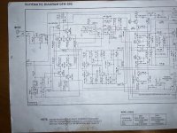
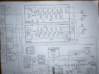
I have a ton of troubleshooting tips, DC operating points etc on my EBFA-565 Annotated Schematic here. Circuit is the same as the GFA-585 with different part numbers.
Check your voltages at the bases of the input transistors, the MPSA13's and MSPSA63's, these should be at less than 5mV, and the voltage here is directly reflected in the output. Also, there are two 1K resistors from the rails to the cascode transistors, and the current through each half of the input stage can be calculated from the drop across this resistor. Similarly, in the VAS stage, there are two 49R9 resistors that you can calculate current for each half of the VAS stage. They should be pretty close.
I have a ton of troubleshooting tips, DC operating points etc on my EBFA-565 Annotated Schematic here. Circuit is the same as the GFA-585 with different part numbers.
If you wanna fix it without a new board, you can abandon the PCB traces and connect the high-impedance nets on bodge wires above the board... Lift the pins of the input LTP and cascode bases, and servo inputs.
This is really helpful, thank you! I'm still a little hopeful that there is an issue with a component since the board around IC101 and the nearby input stage is squeaky clean, with no corrosion. Phloodpants, thanks for the tips about how to check the input and VAS stages. I'm going to do that and report back. I will take a look at the schematic you mentioned (thank you).
Also, one other thing I forgot to mention is that when power is turned off, the offset starts immediately, and for the first 10-15 seconds the rails for the input section are balanced, but then the negative rail drops much faster than the positive. However the rails at the output stage are still balanced and discharge at close to the same rate.
Also, one other thing I forgot to mention is that when power is turned off, the offset starts immediately, and for the first 10-15 seconds the rails for the input section are balanced, but then the negative rail drops much faster than the positive. However the rails at the output stage are still balanced and discharge at close to the same rate.

Yeah, sounds like the servo is trying its best. When you shut off the amp, the power supply for the servo would drain faster than the main power supply.
@Phloodpants I took a look a quick look at the schematic you provided...WOW! So much good troubleshooting information. It's going to take me a bit to check my amp against this.
Tonight I took the measurements mentioned above.
Voltage across 1K rail resistors resistors:
R105: 1.65v when power is on / .09v after about a second when power is turned off
R142: 1.63v when power is on / .70v for about 30 seconds until it gradually decays
Voltage across 49.9 rail resistors resistors:
R118: .93v when power is on / .1v after about a second when power is turned off
R210: .94v when power is on / .1v after about a second when power is turned off
Voltage at base of Q103/Q109: 1.5-5mv, stays in that range when power is turned off
Voltage at base of Q104/Q112: 5-50mv (the first power on it was 5mv, if I powered down and back up it was 50mv), 200mv immediately when turned off then slowly decayed.
Any thoughts about these measurements? When running and settled in, the amp seems to follow within the specs from the schematic above, but there were some differences when powering down. Should I only be concerned with Q103/Q104 which seemed fine, or is Q104/Q112 a clue? The other difference is R142 which held its voltage much longer than the other resistors.
Yeah, those are pretty even currents from positive to negative halves. So that suggests that no components are actually blown, they are doing what they're supposed to.
Everything points to conductive board.
Everything points to conductive board.
You can check the current being supplied by the current source, and that will indicate if the non-inverting side of the LTP input section is seeing approximately equal current. Measure across those the 499R resistors on the current source's output. But you'll probably find it's pretty close. That covers the major building blocks of the amp, as far as balance is concerned.
Note: it's normal and by design for one of the LEDs to be brighter than the other.
Note: it's normal and by design for one of the LEDs to be brighter than the other.
Also it might be helpful to disconnect the servo for the time being, it can cause confusion. And the servo might be confused by electrolyte leakage and drifting around aimlessly. Just lift one leg of the 1K resistor on its output. You should then have an amp with maybe 300mV max offset.
If you lift that 1K resistor, and find that the amp behaves and stays steady, albeit with some offset, then that indicates it's actually the servo causing your offset.
If you lift that 1K resistor, and find that the amp behaves and stays steady, albeit with some offset, then that indicates it's actually the servo causing your offset.
Thats for the hints! This has been a crash course for me in amp diagnostics and I really appreciate your help! Ok, I did some more testing tonight of all of the diodes and resistors on the board and found that D109 and D110 were both open 🙁 I was a little surprised, I thought that diode failure mode was a short, not an open. Looking closer, it looks like Q108 was replaced at some point, so maybe it took out those diodes? I tested the transistor, but it at least tests ok...I may replace anyways. In any case I need to order some parts, and it seems that stablister is going to be a challenge finding... BTW, your suggestion to just replace the boards is not lost on me, but I'm trying to make this a learning experience as much as fixing the amp, so I'd like to exhaust the possibilities until I'm exhausted and either find the cause or just build some new boards.
D109 is a 2-junction stabistor, you should see a 1.2V forward drop with diode test on your meter. If it's the epoxy-blob types, note they are marked with black paint on the anode side, not cathode as one might expect.
D110 is part of the clip detector and shouldn't be doing anything in normal operation... Something bad happened there. If someone was in there already and couldn't fix it, that's could complicate things further.
I totally encourage you to at least try to fix it without a new board, you'll learn a lot. The 565/585 is infamously be-fuddling to work on, and if you can fix one, you can fix anything.
I agree that it looks like something bad happened there 🙂. I tested those diodes 3 ways: they had maybe a couple mv voltage drop, no indication with diode test either way and 1-6 megaohm resistance either direction. I’ll report back after I get the parts.
My sincere apologies for going dark until now. I had some family and job things going on that kept me from this amp, but now I'm baaaack! Here is where I am at:
1: I disconnected the servo as Phloodpants recommended and the offset seems pretty healthy (about 30 mv) when running, but huge offset when powering down.
2: I re-checked the stabisters and I think they are OK.
3: I measured the voltage of the 2 wire signal cable that feeds the two output boards. While running they are both about equal voltage at 1.75v. When I power down they both decay at about the same rate, even though the offset at the speaker terminals is about 10v.
3: I measured the main positive and negative rails at the output boards for voltage decay when powering down and positive / negative decay at the same rate.
So I am completely stumped. How can I have such a big offset at the speakers when the positive / negative voltage from input board seems balanced and the rails at the output boards also seems balanced when the power is turned off.
Any suggestions would be very much appreciated!!!
For those who helped me and those who might encounter a problem like this in the future, I just wanted to bring this to a conclusion. After quite a bit of troubleshooting, I found the issue to be a slightly leaky diode in the voltage gain section. It is now working and sounding great! Thanks to everyone who helped me, I learned a lot and truly appreciate it!
I also wanted to share my experience using AI (ChatGPT) to help me troubleshoot the amp. I am amazed at how far AI has come. First, in the prompt I listed the amp model and make along with a detailed summary of the symptoms. The response was surprisingly good, with some suggestions on places to look and a recommended plan of attack. Then I took a picture of the schematic and uploaded it. ChatGPT could not only read the schematic but could also interpret the functions of the various circuits! Wow! Then I took a picture of the circuit description from the service manual and uploaded it. ChapGPT further refined its suggestions and troubleshooting plan based on this information! While not perfect, the recommendations provided were about 80-90% correct, but more importantly, it provided explanations every step of the way. Truly amazing!
I also wanted to share my experience using AI (ChatGPT) to help me troubleshoot the amp. I am amazed at how far AI has come. First, in the prompt I listed the amp model and make along with a detailed summary of the symptoms. The response was surprisingly good, with some suggestions on places to look and a recommended plan of attack. Then I took a picture of the schematic and uploaded it. ChatGPT could not only read the schematic but could also interpret the functions of the various circuits! Wow! Then I took a picture of the circuit description from the service manual and uploaded it. ChapGPT further refined its suggestions and troubleshooting plan based on this information! While not perfect, the recommendations provided were about 80-90% correct, but more importantly, it provided explanations every step of the way. Truly amazing!
- Home
- Amplifiers
- Solid State
- Help with Adcom GFA585 Pop on Shutdown