Hey everyone,
This is my first post in DIYaudio, typically I post on AudioKarma, but I've been hung up on a particularly tricky problem (for me anyway) with the amplifier section of a Yamaha CR1020, and I'm just looking to reach a few more pros who might be able to educate me on the issue.
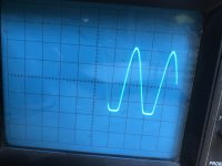
Long story short, after re-capping the receiver, I noticed some distortion in the right channel, and I lost control to adjust the idle current. The left channel amplifier functions perfectly fine. I checked all the voltages compared to the service manual and without a load, everything looked OK, which had me stumped for a few days. Initially, I thought I lost the amplifier bias completely and it was causing crossover distortion. After finally checking things out with the amplifier under load, the problems began to show themselves. Looking at a sin wave under a scope, without a load the amplifier works fine, however, under load, it became clear that the negative half of the wave was clipping.
I'm working with a very superficial knowledge of amplifiers, but I'm thinking, based on the voltages I'm getting with the amplifier under a load, the input or VAS stage is loading the -90V supply for those two sections.
Before I start checking components individually, I'd love to get any thoughts or input from some more experienced folks.
I've attached the voltages I've measured, a picture of the clipping I can see using my scope, and I'll include the link to the other forum thread if you'd like to read the story from the beginning.
Looking forward to getting some feedback. Thanks in advance!
-Ray
Yamaha CR-1020 | Page 2 | Audiokarma Home Audio Stereo Discussion Forums
This is my first post in DIYaudio, typically I post on AudioKarma, but I've been hung up on a particularly tricky problem (for me anyway) with the amplifier section of a Yamaha CR1020, and I'm just looking to reach a few more pros who might be able to educate me on the issue.
Long story short, after re-capping the receiver, I noticed some distortion in the right channel, and I lost control to adjust the idle current. The left channel amplifier functions perfectly fine. I checked all the voltages compared to the service manual and without a load, everything looked OK, which had me stumped for a few days. Initially, I thought I lost the amplifier bias completely and it was causing crossover distortion. After finally checking things out with the amplifier under load, the problems began to show themselves. Looking at a sin wave under a scope, without a load the amplifier works fine, however, under load, it became clear that the negative half of the wave was clipping.
I'm working with a very superficial knowledge of amplifiers, but I'm thinking, based on the voltages I'm getting with the amplifier under a load, the input or VAS stage is loading the -90V supply for those two sections.
Before I start checking components individually, I'd love to get any thoughts or input from some more experienced folks.
I've attached the voltages I've measured, a picture of the clipping I can see using my scope, and I'll include the link to the other forum thread if you'd like to read the story from the beginning.
Looking forward to getting some feedback. Thanks in advance!
-Ray
Yamaha CR-1020 | Page 2 | Audiokarma Home Audio Stereo Discussion Forums
You may want to upload the attachments here (Go Advanced), otherwise you need to be registered at AK to see them.
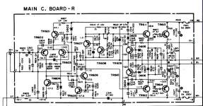
Since there seem to be indications of the input stage being badly out of balance, I would verify that its current source is operating correctly (check R607, 608, 611, voltage drop over D602), as well as check current mirror components (R606, 610, D601, TR604).
If you cannot find any shorted or open transistors in the output stage, I would check R628 and R632 in particular, as well as all solder joints involved.
You said in your post in AK that "when you turn up the volume ---the negative voltage rail drops " .
If you don't have overheating problems due to current overload --as measured --ON the -90 volt rail then its a power supply problem .
If the drop was internal of the voltage rail then that is different but the actual rail is not holding its voltage.
If you don't have overheating problems due to current overload --as measured --ON the -90 volt rail then its a power supply problem .
If the drop was internal of the voltage rail then that is different but the actual rail is not holding its voltage.
Thanks for the suggestions! I'll definitely check those components tonight and let you know what I find.
I'm not ruling out the possibility of a power supply problem, however, considering the left channel works great, which gets the same -90V supply, and the issue is isolated to the right channel, my guess is it's the amp itself.
I'll go through some of the components in the amp tonight and see if I can find the issue.
Also, apologies for not attaching my files to this thread, but I've attached them here so you don't need to reference the AK thread.
Attachments
You mention -90V, but in the schematic I see +-50 for the output stage, and another -58 for the front end? Are both these negative voltages OK? (assuming correct polarity on your scope pic)
I've gone over the table now - voltages at TR613/614 seem extremely dodgy to me, to the point where I suspect one or both may be open (perhaps some bad joints?). I mean, TR614 is 9.2 V E-B, that's not normal, and TR613 seems to be basically turned off. Please verify the pn junctions via diode test on both while powered off, as well as all their connections. R632 as well.
Also, bias seems to be turned up too high... you have over 2.6 V between the emitters of TR607 and TR608, and it should be about 2.36 V. I'd rather have this set too low than too high for now. The pot has hopefully been cleaned to avoid any glitches; this type of bias adjustment is not failsafe.
Also, bias seems to be turned up too high... you have over 2.6 V between the emitters of TR607 and TR608, and it should be about 2.36 V. I'd rather have this set too low than too high for now. The pot has hopefully been cleaned to avoid any glitches; this type of bias adjustment is not failsafe.
Last edited:
Alright just checked all of the components in question out of the circuit, and everything is reading good. Even triple checked the output transistors. I think I'm going to try checking all the other semiconductors out of the circuit tonight to see if anything comes up bad. If all the semiconductors check out, I'll put everything together and solder the output transistors back to the PCB and give it another test. I don't love the design of this. The output transistors serve as the only support for the whole PCB which just hovers above the heatsink. There's a chance I'm losing the connection between the TR614 and the PCB while the PCB is hanging off the transistor.
Check all of the transistors, and still no dice. All the transistors check OK. Soldered the whole amplifier back together, and I'm still having the same problem. I'm beginning to see how this could be a problem with the output transistors, but again, everything is checking good, so I'm at a loss.
Maybe next time I'll lift and check all the resistors? 😕
Maybe next time I'll lift and check all the resistors? 😕
i would compare the good channel with the bad one, measure the voltages and the values of the res.........(perhaps with and without a load at the speaker output).
- Home
- Amplifiers
- Solid State
- Help with a Yamaha CR 1020 amplifier