Hi all!
I was hoping to get some help with my understanding of the crossover in some a/d/s/ MV20/u speakers that I have acquired. The manual does not disclose the crossover points, so I am left to do the detective work on my own. The speaker is comprised of a single 1" tweet, 2 - 1.5" midranges, and 2 - 8" woofers.
Listening to the speakers initially, I felt as if there was a bit of a hole in lower midrange, and that it lacked some "in your face" punch in those frequencies. Since the speakers are bi-wire capable, I decided to remove the binding post straps and hook up only the HI input and play some white noise through it. To my ears, and mostly verified using a crappy free RTA app on my phone, it seemed as if the high pass was set somewhere around 1.5k or so. Switching over to the LOW input with the white noise seemed to verify the seemingly high Low-Mid crossover point of 1.5k-ish, though harder to tell.
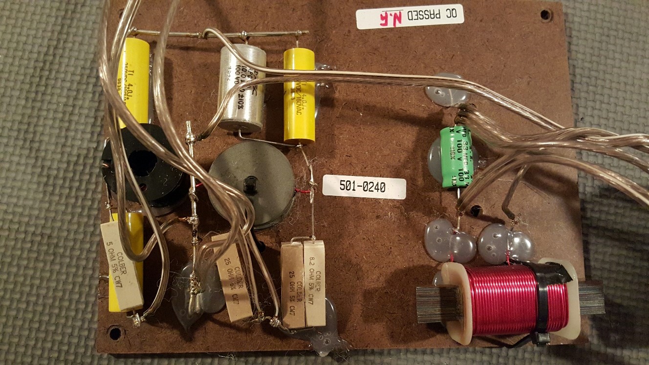
Feeling like there was improvements to be made with the voicing, I decided to make it a small project. I felt like lowering the crossover point to let the mids handle more range might provide me with what I was looking for. Not having any parameters for the drivers, I know I'm flying blind a bit, but after all, earlier ADS speakers like the L780 rated at 150W built utilizing single 1.5" mids were crossed at 650hz. I'm thinking that a pair of them sharing the load could achieve something similar, if not go even lower. So tear the cab apart and dig out the crossover.
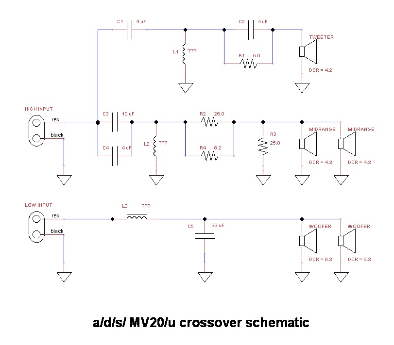
And here's the schematic I drew up:
I don't have any inductor values, and I included the DCRs for the drivers.
I've done some research, but I have limited experience with crossover circuits so hopefully some of you can help with a couple of questions.
First of all, given the information in the schematic, can anyone hazard a guess as to the approximate factory crossover points of this system? I know that without the inductor values known, the exact points cannot be determined, but maybe the capacitor values help?
And secondly, the LOW side is easy to see a 2nd order lowpass configuration in place. But what's going on with the HIGH section? I think I see a 3rd order highpass and resistor for the tweeter, but isn't that resistor usually in series? Does it matter that it is in parallel with capacitor C2? And I believe there to be a 2nd order highpass and an L-pad for the mids, but no lowpass for the mids??? Does that ever happen? What am I missing here?
Thanks in advance!
I was hoping to get some help with my understanding of the crossover in some a/d/s/ MV20/u speakers that I have acquired. The manual does not disclose the crossover points, so I am left to do the detective work on my own. The speaker is comprised of a single 1" tweet, 2 - 1.5" midranges, and 2 - 8" woofers.
Listening to the speakers initially, I felt as if there was a bit of a hole in lower midrange, and that it lacked some "in your face" punch in those frequencies. Since the speakers are bi-wire capable, I decided to remove the binding post straps and hook up only the HI input and play some white noise through it. To my ears, and mostly verified using a crappy free RTA app on my phone, it seemed as if the high pass was set somewhere around 1.5k or so. Switching over to the LOW input with the white noise seemed to verify the seemingly high Low-Mid crossover point of 1.5k-ish, though harder to tell.
Feeling like there was improvements to be made with the voicing, I decided to make it a small project. I felt like lowering the crossover point to let the mids handle more range might provide me with what I was looking for. Not having any parameters for the drivers, I know I'm flying blind a bit, but after all, earlier ADS speakers like the L780 rated at 150W built utilizing single 1.5" mids were crossed at 650hz. I'm thinking that a pair of them sharing the load could achieve something similar, if not go even lower. So tear the cab apart and dig out the crossover.
And here's the schematic I drew up:
I don't have any inductor values, and I included the DCRs for the drivers.
I've done some research, but I have limited experience with crossover circuits so hopefully some of you can help with a couple of questions.
First of all, given the information in the schematic, can anyone hazard a guess as to the approximate factory crossover points of this system? I know that without the inductor values known, the exact points cannot be determined, but maybe the capacitor values help?
And secondly, the LOW side is easy to see a 2nd order lowpass configuration in place. But what's going on with the HIGH section? I think I see a 3rd order highpass and resistor for the tweeter, but isn't that resistor usually in series? Does it matter that it is in parallel with capacitor C2? And I believe there to be a 2nd order highpass and an L-pad for the mids, but no lowpass for the mids??? Does that ever happen? What am I missing here?
Thanks in advance!
Attachments
Hi Yacho,
I really suggest you try out XSim for your crossover discovery. It is a very good simulator and easy to use. Even if you don't have exact values you should be able to use it to learn about what's going on that way.
Best,
Erik
I really suggest you try out XSim for your crossover discovery. It is a very good simulator and easy to use. Even if you don't have exact values you should be able to use it to learn about what's going on that way.
Best,
Erik
Ballpark figures, usually 3 way speakers have a tweeter crossover point around 3 to 5 kHz as a minimum. The low end of hte midrange is anywhere from 200Hz to 500 Hz. My guess, given their small size is 350 Hz or higher.
Input what you know into XSim, maybe use a resistor instead of a real speaker and you can probably come to some reasonable guess.
The bass inductor is probably 2mH or greater. The coil in the tweeter anywhere from 0.3 to 0.8mH.
A very useful tool for you may be the Dayton Audio DATS which can measure caps and inductors directly, as well as speaker impedances.
Purchase with OmniMic for $300, by itself for $99. If I was going to go down the road you are, I'd do a complete analysis of the individual drivers before doing anything else. You never know how bad the original design was otherwise.")
Cheaper alternatives to OmniMic are to use Room EQ Wizard with the $12 Dayton measurement microphone. There's also DIY alternatives to DATS, but how much of this do you want to DIY?
Best,
Erik
Input what you know into XSim, maybe use a resistor instead of a real speaker and you can probably come to some reasonable guess.
The bass inductor is probably 2mH or greater. The coil in the tweeter anywhere from 0.3 to 0.8mH.
A very useful tool for you may be the Dayton Audio DATS which can measure caps and inductors directly, as well as speaker impedances.
Purchase with OmniMic for $300, by itself for $99. If I was going to go down the road you are, I'd do a complete analysis of the individual drivers before doing anything else. You never know how bad the original design was otherwise.
Cheaper alternatives to OmniMic are to use Room EQ Wizard with the $12 Dayton measurement microphone. There's also DIY alternatives to DATS, but how much of this do you want to DIY?
Best,
Erik
OK, well blow me down. This is not a 3 way design. It's an inverted 2.5 way design!
Usually, in a 2.5 way, the midrange has no high pass filter, and does double duty as bass. This is the opposite. The midrange has no external/explicit low pass filter. Any low pass filtering of the midrange units is being accomplished by the inherent inductance of them. The midrange only uses a 2nd order high pass filter and padding. This makes measuring the midrange impedance rather critical.
Best,
Erik
eriksquires, Thanks for taking a hack at it!
And thanks for pointing me towards the correct tools for the job. I'll be teaching myself Xsim tonight.
I am also used to the "ballpark" 3-way crossover frequencies of 500 and 5k, so this is what originally piqued my concern, but I've never run into an inverted 2.5-way. Is there a general design consideration that when letting the midrange drivers extend out to their highest natural frequencies, you should keep the low crossover point up as well?
And listening to the tweeter itself, it is clearly not in "super tweeter" range. Shouldn't the high end be a complete mess allowing two 1.5" mids to run free like that with a tweeter that is (to the ear) operating at normal tweeter frequencies? Because, the high end is actually really good. Interesting stuff. I see a Parts Express order in my future.
I'm making up the term "Inverted 2.5 way" i'm afraid. While a "2.5 way" speaker is a commonly used term, this is a little upside down, which is why I made up this term. It's really not a very common arrangement. To fully understand what was intended you'll need to measure the individual drivers electrically and acoustically, as well as those inductors. Once you have that then XSim can perfectly model the combined drivers and crossover.
My guess, based on the arrangement, is that they wanted the treble to be covered by the 3 drivers, but the midrange only by the outer one's. This could make the speaker beam at mid to high frequencies so it acts more like a ribbon or line source. You get more clarity at the seated position as it beams, but a more restrictive vertical listening position. Not a negative, but a design choice. This type of restrictive dispersion can really make speakers sound better in untreated rooms.
What is it you want to get out of this project, by the way? Personally, I think the best you can do is learn about speaker analysis and design. That is, investing in yourself and your own capabilities have a much higher return on investment than re-making or tuning up an older speaker. Of course, one goes with the other.
Best,
Erik
While a "2.5 way" speaker is a commonly used term, this is a little upside down, which is why I made up this term. It's really not a very common arrangement. To fully understand what was intended you'll need to measure the individual drivers electrically and acoustically, as well as those inductors. Once you have that then XSim can perfectly model the combined drivers and crossover. My guess, based on the arrangement, is that they wanted the treble to be covered by the 3 drivers, but the midrange only by the outer one's. This could make the speaker beam at mid to high frequencies so it acts more like a ribbon or line source. You get more clarity at the seated position as it beams, but a more restrictive vertical listening position. Not a negative, but a design choice. This type of restrictive dispersion can really make speakers sound better in untreated rooms.
What is it you want to get out of this project, by the way? Personally, I think the best you can do is learn about speaker analysis and design. That is, investing in yourself and your own capabilities have a much higher return on investment than re-making or tuning up an older speaker. Of course, one goes with the other.
Best,
Erik
My guess, based on the arrangement, is that they wanted the treble to be covered by the 3 drivers, but the midrange only by the outer one's. This could make the speaker beam at mid to high frequencies so it acts more like a ribbon or line source. You get more clarity at the seated position as it beams, but a more restrictive vertical listening position. Not a negative, but a design choice. This type of restrictive dispersion can really make speakers sound better in untreated rooms.
Ding! Ding! Ding! We have a winner!!!
Here's a quote directly from the a/d/s/ MV20/u manual:
"One of the unique features of the MV series is the use of vertically symmetrical driver arrays and unique crossovers which combine to focus the vertical dispersion of the midrange and high frequencies. This reduces the undesired reflections from the floor and ceiling which confuse the musical image in conventional loudspeakers."
Of course, I had read that before, but had largely regarded it as consumer marketing fluff until your post jogged my memory. Whereas a/d/s/ simply states this info wrapped by mostly "rah! rah! a/d/s/!" verbage in their manual, you have explained it brilliantly. Thanks!
Also, BTW, XSim is clearly the way to go for speaker system design software. So many of these types of simple yet amazing programs fly under the Google search radar that it's impossible to get there without the good ol' word of mouth via actual humans. Double thanks for that!
And, why am I doing this project? Well, it started out as just a possible tweak to the midrange, but it is already expanding my knowledge of speaker systems and crossover design. I have, in the past, done some simple re-voicing of older ADS models to suit my tastes by basic alteration of mid and tweeter series resistors, but this would be my first attempt to slide crossover points around. And even though it is way more involved, I'm still going to go after it. I might have success with this project, and I might turn all the drivers into dust, but either way I will learn a ton doing it. So I guess it is based quite a bit on personal investment and the never-ending quest for personal knowledge.
And, why am I doing this project? Well, it started out as just a possible tweak to the midrange, but it is already expanding my knowledge of speaker systems and crossover design. I have, in the past, done some simple re-voicing of older ADS models to suit my tastes by basic alteration of mid and tweeter series resistors, but this would be my first attempt to slide crossover points around. And even though it is way more involved, I'm still going to go after it. I might have success with this project, and I might turn all the drivers into dust, but either way I will learn a ton doing it. So I guess it is based quite a bit on personal investment and the never-ending quest for personal knowledge.
- Status
- This old topic is closed. If you want to reopen this topic, contact a moderator using the "Report Post" button.
- Home
- Loudspeakers
- Multi-Way
- Help with a/d/s/ MV20/u crossover please!