I recently purchased a "Sophia" push pull 6CA7 amp, to have something again to play with. After repairing a blown screen regulator, the amp biased the output tubes reasonably and played. Then I thought I'd do a frequency sweep...
It's down 6db at 20kHz, falling continuously from 1k. I traced that behavior to the 6U8 pentode input stage. I'm an EE with 40 years analog circuit experience and it has me well over a barrel.
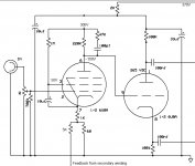
1. I looked up the schematic and other 6U8 designs; it's nothing special; 220k on the plate to B+, 1k cathode to 68 ohm to ground. 5k to the 68 for feedback. 1M from B+ to screen with 10uF bypass, +50V across that cap.
2. I pulled the output tubes, running just the 6U8s alone - no change.
3. There's some 1nF-47k across the 220k. I pulled the 1nF - no change.
4. I disconnected the triode paraphase driver grid from the plate - no change.
5. I replaced the 10uF screen bypass with 0.1 - no change.
6. Noticing B+ was a little high at 375V, I reduced it to 300V. No change.
7. Added DC blocking caps to input grid circuit (In case the FG used has some residual DC) - no change...
8. Refreshed all the nearby socket and component solder connections - no change.
9. I lifted the PCB to have a look at the top side components and stuck in just one 6U8 tube (no output tubes). I *thought* I saw an increasing amplitude with frequency, before really ripping into the circuit; but I was so batty over it at that point I may have been mistaken. (is that what it does normally - hence the 1nF-47k in // with the 220k plate?)
10. ~1mA current flows through the tube; 220V drop across the 220k and 1V across the 1k.
All 4 of the 6U8s I own do this and it happens in both (stereo) sockets. Tubes check OK on my tester, tubes from two separate ebay sellers claiming tubes "test strong".
Amp was found by a non-technical ebay seller at an estate sale; I'm convinced it's haunted by the former owner who's having a good chuckle at my expense up there in heaven...
What could possibly be the matter with this input stage!?! As I sweep my FG to 20kHz, sine amplitude at the plate drops from 40 - 50V down to <20 - as displayed and measured on an Oscilloscope. I'm struggling to understand how such a simple circuit could possibly perform this way.
If it was just ONE tube, of the lot or socket...but it's all of them. Some factor is clearly dominant and I cant seem to find it. Tube socket morphed into a capacitor over time (in both sockets?)? Some mechanical issue with the PCB (in both sockets?) or because the tubes poke up through the chassis surface? Please help!
Thanks, from a new-ish member.
Joe
It's down 6db at 20kHz, falling continuously from 1k. I traced that behavior to the 6U8 pentode input stage. I'm an EE with 40 years analog circuit experience and it has me well over a barrel.
1. I looked up the schematic and other 6U8 designs; it's nothing special; 220k on the plate to B+, 1k cathode to 68 ohm to ground. 5k to the 68 for feedback. 1M from B+ to screen with 10uF bypass, +50V across that cap.
2. I pulled the output tubes, running just the 6U8s alone - no change.
3. There's some 1nF-47k across the 220k. I pulled the 1nF - no change.
4. I disconnected the triode paraphase driver grid from the plate - no change.
5. I replaced the 10uF screen bypass with 0.1 - no change.
6. Noticing B+ was a little high at 375V, I reduced it to 300V. No change.
7. Added DC blocking caps to input grid circuit (In case the FG used has some residual DC) - no change...
8. Refreshed all the nearby socket and component solder connections - no change.
9. I lifted the PCB to have a look at the top side components and stuck in just one 6U8 tube (no output tubes). I *thought* I saw an increasing amplitude with frequency, before really ripping into the circuit; but I was so batty over it at that point I may have been mistaken. (is that what it does normally - hence the 1nF-47k in // with the 220k plate?)
10. ~1mA current flows through the tube; 220V drop across the 220k and 1V across the 1k.
All 4 of the 6U8s I own do this and it happens in both (stereo) sockets. Tubes check OK on my tester, tubes from two separate ebay sellers claiming tubes "test strong".
Amp was found by a non-technical ebay seller at an estate sale; I'm convinced it's haunted by the former owner who's having a good chuckle at my expense up there in heaven...
What could possibly be the matter with this input stage!?! As I sweep my FG to 20kHz, sine amplitude at the plate drops from 40 - 50V down to <20 - as displayed and measured on an Oscilloscope. I'm struggling to understand how such a simple circuit could possibly perform this way.
If it was just ONE tube, of the lot or socket...but it's all of them. Some factor is clearly dominant and I cant seem to find it. Tube socket morphed into a capacitor over time (in both sockets?)? Some mechanical issue with the PCB (in both sockets?) or because the tubes poke up through the chassis surface? Please help!
Thanks, from a new-ish member.
Joe
Last edited:
That's equivalent to around 18pF across the 220k. Try a different kind of plate resistor.
You are using a high impedance, attenuator scope probe, properly adjusted, right?
Try using a x100 probe.
You are using a high impedance, attenuator scope probe, properly adjusted, right?
Try using a x100 probe.
Last edited:
Your scope is shunting the signal or there is a lot of miller capacitance in the circuit, or a combination of both.
That circuit has a very high output impedance.
That circuit has a very high output impedance.
Thanks, guys. The scope loading maybe, but the overall fully populated working amplifier exhibits the exact same performance - it's down <50% in output amplitude at 20kHz.
The compensation RC network rolls off much lower than that open loop. The +/-3dB spec at 35kHz could be viewed as -6dB at 35kHz, even if it's met. Could be normal for the output transformer.
Last edited:
Try lowering the plate resistor and G2 resistor you will lower the gain but if the problem is from stray capacitances you should see a better response. It can help if we can see a photo of the suspect circuit There are lots of folks in this place that will help if there is something to see. You can halve those resistors and you will be still in the recommended specs of the pentode section.
More info
Ok, here's the schematic I'm working with. I could run the input pentode in triode mode, FAIC, as I believe I have plenty of drive from a Logitech duet. I'd like to modify to get reasonably flat frequency response - which I assume all other nearly identical 6U8 designs achieve, or they wouldnt be used... Just dont know what's up with these instances?
Ok, here's the schematic I'm working with. I could run the input pentode in triode mode, FAIC, as I believe I have plenty of drive from a Logitech duet. I'd like to modify to get reasonably flat frequency response - which I assume all other nearly identical 6U8 designs achieve, or they wouldnt be used... Just dont know what's up with these instances?
Attachments
Open loop, the compensation rolls off the response at ~7kHz at 20dB/decade.
Then it reaches an asymptote of around -15dB due to a zero at ~34kHz.
Maybe the 37dB closed loop gain is too high to extend this response very much.
Then it reaches an asymptote of around -15dB due to a zero at ~34kHz.
Maybe the 37dB closed loop gain is too high to extend this response very much.
Last edited:
So I pulled the 1nF and didnt see any effect. With just the tube running - no output tubes, no signal to feedback. It seems that compensation is being overrun by something else?
Am I making the mistake that the whole amp will be flat, even if the input pentode isnt, due to global feedback? I'm still suspicious - because it isnt - and it looks like the speaker output feedback wiring cables havent been clipped by anyone.
Here's a similar circuit. I bet the pentode output sails flat past 20kHz no problem, though I really dont know... Seems to be a popular circuit.
If I wanted to sacrifice gain for bandwidth, would I be best off changing plate and G2 resistors as suggested, or going to triode operation? I have no idea what an appropriate resistor value would be for this tube to tie G2 to plate. Not a popular thing to do, apparently.
Thanks again,
Joe
Attachments

Hi Joe,
Are you able to simplify any possible external influences:
- short across the 68 ohm feedback node.
- remove the 47k/100pf shelf network
- load the cathodyne stage with just grid leaks to 0V from the output stage.
- use at least a 10:1 probe (10Meg input) that has been confirmed flat response with your signal generator when probing the input pentode grid (ie. after the input pot).
- lower the B+ from 300V, or lower the pentode anode from 100V down to under 90V (the 6U8 heater-cathode limit).
- measure output signal level across output stage grid leak (preferably with similar probe across the other grid leak to ground to maintain balanced output on the cathodyne).
Maybe not an easy option - loan a 6EA8 and swap out the 6U8. The 6EA8 is same socket format and heater, and had a better performance in a recent amp I was playing with where I started by using a 6U8 in your configuration.
Ciao, Tim
Last edited:
3. There's some 1nF-47k across the 220k. I pulled the 1nF - no change.
4. I disconnected the triode paraphase driver grid from the plate - no change.
Image in #7 shows 100pF (not 1n) and a cathodyne (not paraphase).
I expect a high-NFB amp to need a roll-off before it gets into OT resonances; and I expect that poking high-impedance circuits with meter/'scope will slug the response. The effect can be estimated but foiled by practical issues.
The overall NFB function can be checked by shorting the 68r. If nothing changes, the NFB is broken somewhere.
What a disaster now -
OK, I thank everyone for the insights and I've learned some things
1. The scope probe does load these types of circuits, however it's the only scope I have. I'm convinced by seeing a different frequency response (less droop with frequency) when observing the cathode output of the cathodyne section, versus the plate.
2. This allowed me to see the effect of the 1nF - 47k shelving circuit, which was being cloaked by the scope probe. I'll keep this in mimd when probing high impedence circuits like these in the future!
3. Nevertheless I discovered a parasitic oscillation at around 200kHz that only happens with the volume control around midspan. Great. Happens whether the shelving circuit is connected or not -
4. I went for running the pentode section in triode mode by tying G2 to the plate through a 27K resistor. That's just a guess, as this isnt a popular thing to do.
5. I attempted to mitigate the gain loss by bypassing the 1k cathode resistor with a 180uF Oscon with a 33 uF film in parallel. Again a guess, using parts I happened to have on hand. There's 1.4V DC across this 1K // cap combination. I take it ~1.4 mA going through the pentode section.
6. The amp plays albeit at less than full output with something like an iPod headphone source turned all the way up. It measures better than it did with the pentode and shelving circuit, but still is down 10% voltage wise at 20kHz (versus 2K) using 8 Ohm resistive loads. Soundwise is OK, but I havent tested it yet with the speakers I'll be listening to. Because...
7. Now it has an audible hum at 60Hz, regardless of volume control position. If I pull the 6U8s, and leave just the output tubes running with their -33V grid bias, dead silent. Pentode section running in triode mode is the source I believe and the zener regulated 300V supply to its 220K plate resistor has a fraction of a mV of such noise. Same with the RC coupled supply to the triode cathodyne section, yet by then the plate output has 120mV of this 60Hz AC hum on it that's definitely sawtooth in shape. The cathode output has same but at much less amplitude, the imbalance shows up in the amp output.
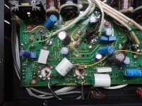
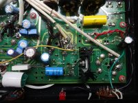
I've ripped this amp to shreds going back and forth between all that I'm trying to simply make it work well. Whenever I exchange a component, up comes the circuit etch with it. I cant see closely very well anymore so I need magnifiers and with those, I cant see where the body of the soldering iron is - I end up burning anything adjacent to the point of work - including two "special Sophia Electric 0.22uF" coupling caps to a dead short. The PCB designer provided additional holes for different size coupling caps - but no plated through holes which could take a little beating - so those connection points are all shot. I'm jumping directly to the tube sockets now and the pads of any top side component pin.
I'm pretty embarrassed to post photos and with 1/2 the components topside and half bottom side, unsure if anyone would take the time to work through all the connections anyway. Oh well, here goes -
I am a neophyte as - again - I'm stumped by "How can this signal possibly be there when the power supply to this tube is, er, quite clean!?!" Disconnect the input coax wiring to the 6U8 input grid - no change. What, do I have to go to DC on the filaments now? I mean it's gigantic! Did I break all the 6U8s? What could possibly be the source of this; of course I put everything back to pentode and it still does it, so everything back to triode again. Yes, both tubes of the stereo pair do the same and no matter what tube.
Should it be this hard? I could be doing a LOT better than this for the $500 or so I've got into this POS. I thought I'd try to fix it and resell, but it's so torn up now inside I couldnt sell it to anyone in good consciousness.
Appreciate if anyone could help me rid the amp of this hum, so I can actually use it to play music through. Thanks,
OK, I thank everyone for the insights and I've learned some things
1. The scope probe does load these types of circuits, however it's the only scope I have. I'm convinced by seeing a different frequency response (less droop with frequency) when observing the cathode output of the cathodyne section, versus the plate.
2. This allowed me to see the effect of the 1nF - 47k shelving circuit, which was being cloaked by the scope probe. I'll keep this in mimd when probing high impedence circuits like these in the future!
3. Nevertheless I discovered a parasitic oscillation at around 200kHz that only happens with the volume control around midspan. Great. Happens whether the shelving circuit is connected or not -
4. I went for running the pentode section in triode mode by tying G2 to the plate through a 27K resistor. That's just a guess, as this isnt a popular thing to do.
5. I attempted to mitigate the gain loss by bypassing the 1k cathode resistor with a 180uF Oscon with a 33 uF film in parallel. Again a guess, using parts I happened to have on hand. There's 1.4V DC across this 1K // cap combination. I take it ~1.4 mA going through the pentode section.
6. The amp plays albeit at less than full output with something like an iPod headphone source turned all the way up. It measures better than it did with the pentode and shelving circuit, but still is down 10% voltage wise at 20kHz (versus 2K) using 8 Ohm resistive loads. Soundwise is OK, but I havent tested it yet with the speakers I'll be listening to. Because...
7. Now it has an audible hum at 60Hz, regardless of volume control position. If I pull the 6U8s, and leave just the output tubes running with their -33V grid bias, dead silent. Pentode section running in triode mode is the source I believe and the zener regulated 300V supply to its 220K plate resistor has a fraction of a mV of such noise. Same with the RC coupled supply to the triode cathodyne section, yet by then the plate output has 120mV of this 60Hz AC hum on it that's definitely sawtooth in shape. The cathode output has same but at much less amplitude, the imbalance shows up in the amp output.
I've ripped this amp to shreds going back and forth between all that I'm trying to simply make it work well. Whenever I exchange a component, up comes the circuit etch with it. I cant see closely very well anymore so I need magnifiers and with those, I cant see where the body of the soldering iron is - I end up burning anything adjacent to the point of work - including two "special Sophia Electric 0.22uF" coupling caps to a dead short. The PCB designer provided additional holes for different size coupling caps - but no plated through holes which could take a little beating - so those connection points are all shot. I'm jumping directly to the tube sockets now and the pads of any top side component pin.
I'm pretty embarrassed to post photos and with 1/2 the components topside and half bottom side, unsure if anyone would take the time to work through all the connections anyway. Oh well, here goes -
I am a neophyte as - again - I'm stumped by "How can this signal possibly be there when the power supply to this tube is, er, quite clean!?!" Disconnect the input coax wiring to the 6U8 input grid - no change. What, do I have to go to DC on the filaments now? I mean it's gigantic! Did I break all the 6U8s? What could possibly be the source of this; of course I put everything back to pentode and it still does it, so everything back to triode again. Yes, both tubes of the stereo pair do the same and no matter what tube.
Should it be this hard? I could be doing a LOT better than this for the $500 or so I've got into this POS. I thought I'd try to fix it and resell, but it's so torn up now inside I couldnt sell it to anyone in good consciousness.
Appreciate if anyone could help me rid the amp of this hum, so I can actually use it to play music through. Thanks,
Attachments
Last edited:
It seems Chinese amps are a pain to repair in general, I have an Audio Space Galaxy 34 that had / has similar issues, there is no schematic for it that has been released, the manufacturer copied the circuits (with slight modifications) from other manufacturers, but refuses to allow others to repair their failures.
Every time a board is moved, the fragile wires just break at the solder joint, making a small repair snowball into more problems as you work on it.
The quality of the circuit boards is better on this one at least, the holes are through plated at least.
One possible issue is that some of the bypass wires don't follow the same path as the original trace, possibly picking up hum. The other suggestion I have, since the original schematic is available, restore it to the original circuit.
Get a better magnifier, and a smaller soldering Iron, to reduce the damage to the PC board.
My amp started out with a broken ground to the ground buss, and a "tech" took half of the boards out, put them back(missing some components) and finally gave up, returning it unrepaired. There are still a few problems, but the amp part is now working properly at least.
Last edited:
If looking at the freq response somewhere inside the cct the NFB needs to be disconnected. Otherwise we see the result of the NFB & the stage in test.
The plate of the 6U8 pentode is inside the NFB loop.🙂
If NFB is left connected & the test amp is driving a loudspeaker we see a pretty good inverted trace of the loudspeaker impedance. The test should be done while driving a resistive load.🙂
The probe used needs to have very low capacity while checking a pentode voltage amp. The source for the probe is simply the plate resister in parallel with the rp of the tube.
The cct used here the triode phase splitter looks like a very high impedance since a very large part of that stage gain appera as local NFB. So under ordinary conditions applies only a slight load to the previous stage.
A better place to connect the probe would be the cathode of the following phase splitter triode. That will result in a much more accurate reading.
I fixed the hum, which was my fault. The pictures show 500 ohm resistors' implementation of triode mode on the output tubes. The OEM didnt provide enough negative bias to run the tubes this way, so I jumped a resistor in the PI filter to get 8 more volts, which set the bias not so hot - with the bias adjustment pots all the way open!
This was the source of the 60 hz sawtooth. So I pulled out the jump, built a voltage doubler which gave me 50V vs 25, and adjusted the pots to put -33V to the output tubes. No more hum.
The amp plays at a decent loudness level using a Logitech duet as source, with its volume all the way up, using the amp's volume control. I'm 63 and can afford to sacrifice how loud it goes for other desirable qualities, like that which (they say) triode mode provides.
Thanks to everyone who helped me out here. I'll post a conclusion in case anyone is interested, then start another thread with something else I'll be doing on this 6CA7 tube amplifier.
This round, I learned;
1. If you're going to work on modern, PCB based tube amplifiers that originated in China, you need to use a good soldering iron. Preferably a temperature controlled one, that doesnt lift etch at every possible opportunity.
2. If you're going to use an oscilloscope to look at signals within typical audio design practice, you need to account for the capacitive loading it places on the impedance of the circuit. Such as that 100K plate resistor in a 12AX7 based gain stage. Always probe at the cathode circuit, if a voltage signal is available there.
3. Amplifiers like this were perhaps "voiced" by the addition of a frequency shelving circuit placing a perception in priority over measurement. There's nothing wrong with undoing such voicing if that makes the amplifier measure better and YOUR ears agree. If the shelving was necessary to achieve flat frequency response because of the output transformer design, that should show up in a frequency response sweep.
4. There's an alternate tube available that's a better performer than the 6U8, the 6EA8. Perhaps as well running the pentode section in triode mode.
5. You can run one of these 6U8 pentodes in triode mode by simply connecting G2 to the plate via an appropriately sized resistor. I used 27K and it sounds pretty good. Acknowledging I could do better on optimizing this value.
6. Attempting to make any changes to the OEM's circuit design can leave you stranded, with the only option that wont burn your tube set is to put it back as originally built. Or get lucky and be able to easily add additional components to address it.
7. Probably need to start documenting "them changes". The little Sony camera I used to snap the two attachments above does a nice job, You can see the jumper wire in place that, when removed, eliminated the hum problem.
8. I called the amp a POS earlier, but I have to admit the power supply section has gone through a few cycles in the last couple of weeks without issue. Cold turn on, hot turn on, with no output tubes installed... I half expect "arc-flash!" whenever I turn it back on, but that hasnt happened despite ample opportunity. That part always works and I appreciate that. However those mid-span parasitic oscillations in its stock form...
9. I learned something about and gained experience with biasing the output tubes, which became necessary with every change to the power output tube circuitry. I was gearing up to install individual bias adjustments on the output tubes and may still do.
10. I confirmed what I'd thought earlier; these pentode inputs helped build a product that could accommodate a wide range of who knows what a customer would want to connect to it. If you're only going to connect the amp to one thing EVER and that thing happens to be a modern solid state device, chances are good you dont even need all that gain. You could pitch the pentode input in favor of a triode, take the gain hit and still listen comfortably. Well, at least I can.
Thanks and Appreciations,
Last edited:
- Status
- Not open for further replies.
- Home
- Amplifiers
- Tubes / Valves
- Help with 6U8 Pentode section - Stumped!!!