Normally you will produce a good speaker if you consider the limits of all the compromises and keep them within proven reason.
...
A suggestion is to calculate the minimum quantities for each and make sure you can fit these together into a system, then branch outward from there as the compromises will be more apparent. Once these conditions are satisfied, the electrical networks should almost build themselves as the result will be more or less known.
OK. Which minimum quantities should I calculate?
I'm leaning towards trying a 2-way passive since it's relatively simple and inexpensive, and I'll learn along the way.
I'm thinking the tweeter should be on a 2nd or 3rd order and so should the midrange to avoid getting into cone breakup area (should I go with a 1st order).
AllenB suggested the tweeter be on a higher order than the midrange. So 3rd order for tweeter and 2nd order for midrange.
3rd order Butterworth for this tweeter, at 2500Hz:
Here's what I envision as next steps:
I'm thinking the tweeter should be on a 2nd or 3rd order and so should the midrange to avoid getting into cone breakup area (should I go with a 1st order).
AllenB suggested the tweeter be on a higher order than the midrange. So 3rd order for tweeter and 2nd order for midrange.
3rd order Butterworth for this tweeter, at 2500Hz:
C1=8.66uF
C2=25.98uF
L1=0.23mH
I've asked a potential supplier what he has available around these values.C2=25.98uF
L1=0.23mH
Here's what I envision as next steps:
- Get feedback here and adjust this plan
- Get parts for the tweeter network (above) and for a 2nd order LR network for the midrange without the horn
- Build 3rd order network for tweeter, measure frequency response, confirm it's doing what I expected.
- Build horn for the midrange, measure, re-run numbers for the network.
I don't think I said as much as that. Have you decided how those horns are going to fit together?AllenB suggested the tweeter be on a higher order than the midrange.
I don't think I said as much as that. Have you decided how those horns are going to fit together?
What do you mean by "fit together"?
I think it's premature to expect to finalise a crossover without first building the speaker. It could be simulated, but I think it would be easier and more accurate to use actual results (unless the design process is thorough), and it's something I'd do either way.
If you're just looking to get the tweeter operating so you can begin assessing it by listening then perhaps you could try a second order filter at a moderate frequency (I hear 2k is not unreasonable for the TPL) though I'd expect you'd want to vary this filter considerably to see what the driver can do, keeping in mind that it's difficult to tell too much without a properly blended lower range.
When it comes to measuring it might be more helpful to use a bare minimal crossover if any so it gives you useful data for the sim.
Is it a bad idea to add two capacitors in parallel to get close to the capacitance I need? Example: per the calculations I would need 8.7uF cap. If I add in parallel a 3.9uf + 4.7uF I would get 8.6uF.
This would be for C1 in a 3rd order BW network.
This would be for C1 in a 3rd order BW network.
Over the weekend I spent some time looking into this. I'm taking away using Bagby's Passive Crossover Designer tool is probably my best alternative. Would you agree?
And to properly use the tool I need to measure my drivers, export the frd and zma files to load into the tool, and take it from there. Is that a good path?
And to properly use the tool I need to measure my drivers, export the frd and zma files to load into the tool, and take it from there. Is that a good path?
Is it a bad idea to add two capacitors in parallel to get close to the capacitance I need? Example: per the calculations I would need 8.7uF cap. If I add in parallel a 3.9uf + 4.7uF I would get 8.6uF.
This would be for C1 in a 3rd order BW network.
May I ? I don't think it's a bad idea ! The caps model will make more difference here than 0.4 uF imho ! But you should be able to find 9 uF 1 or 2% acuracy the day you're will be defintly ok with your filter and when it will be your last priority...🙂
A step in the right direction, definitely.Is that a good path?
Bagby's Passive Crossover Designer tool is probably my best alternative. Would you agree?
Very good tutorial on the PCD toolset.
Simple Loudspeaker Design ver2 Dave Dal Farra
http://audio.claub.net/software/DaveDalFarra/Simple Loudspeaker Design ver2.pdf
The free schematic-based crossover tool Xsim is popular for horn speakers which break the standard box flow.
Good.
I'll do the TPL first. How should I set up driver and mic for the purpose of measuring response towards crossover design?
Does it matter where I place the TPL?
Should I place the mic 10cm from the AMT, on-axis, in the middle of the AMT height? Or further away?
Gate the measurement? By how much?
I'll do the TPL first. How should I set up driver and mic for the purpose of measuring response towards crossover design?
Does it matter where I place the TPL?
Should I place the mic 10cm from the AMT, on-axis, in the middle of the AMT height? Or further away?
Gate the measurement? By how much?
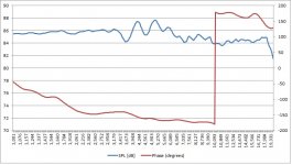
Here's the measured TPL-150H response.
TPL was mounted vertically, away from reflecting surfaces. Mic was inside the waveguide and 3" away from the front of the AMT, on axis, in the middle. I used REW, from 1 to 20kHz, gated with FDW of 10 cycles.
Is this OK to use as input into Bagby's Passive Crossover Designer?
TPL was mounted vertically, away from reflecting surfaces. Mic was inside the waveguide and 3" away from the front of the AMT, on axis, in the middle. I used REW, from 1 to 20kHz, gated with FDW of 10 cycles.
Is this OK to use as input into Bagby's Passive Crossover Designer?
Attachments
Those appear to have the treble peak like the old AMT. I'm not sure that can be completely fixed.
Those appear to have the treble peak like the old AMT. I'm not sure that can be completely fixed.
Could you be more specific about what you mean by "treble peak"?
peaks and dips around 5k are less than 2 dB and L. has active EQ if needed.
Is it not better to measure it at the mouth of the horn on axis, then 1 meter, then at the seat spot to have an idea ?
I assume for XO, measurements are maid at 1 meter for the trebles and mediums ?
Is it not better to measure it at the mouth of the horn on axis, then 1 meter, then at the seat spot to have an idea ?
I assume for XO, measurements are maid at 1 meter for the trebles and mediums ?
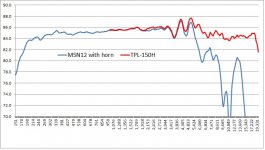
I built a dummy rectangular tractrix horn for the M5N12 out of foam, and measured the driver. Response is plotted below. It looks so good it is making me wonder if I'm measuring appropriately.
Mic was set 12" from the horn mouth, gated FDW at 10 cycles, response smoothed at 1/48.
It is very suspicious to me the exact same response as the TPL was measured, even the ripples at 4-5kHz.
So assuming the measurement was right, next step is to input both frd ccurves into the Passsive Crossover Designer. BUT, do measurements look right?
Thanks in advance for the input!
Attachments

- Status
- Not open for further replies.
- Home
- Loudspeakers
- Multi-Way
- Help with 2-way crossover for TPL-150H and Faital M5N12