Hi,
I've just finished a small el84 pp power amp inspired by the vacuum state pp1c. The little amp worked perfectly from the first power on and has a nice, fast detailed and very clean sound, way better then what i expected. The only comment i have is that is a little bass shy and less detailed in the bass then the pp6v6 i have and which uses the same trannies (from an old Lafayette la224B).
Now i want to do some testing and finetuning and would like your critique and advise. I've got a scope (philips pm3230), function generator (GW gfg-8015G) and a testload (8R/50W in parallel with 1,8uF times two).
Now here's my question:
-What to measure/test and how?
-What to try? (maybe some feedback like 3-6db?)
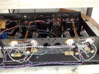
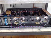
attached are the schematics (with measured voltages) and some pics.
thanks,
Joris
I've just finished a small el84 pp power amp inspired by the vacuum state pp1c. The little amp worked perfectly from the first power on and has a nice, fast detailed and very clean sound, way better then what i expected. The only comment i have is that is a little bass shy and less detailed in the bass then the pp6v6 i have and which uses the same trannies (from an old Lafayette la224B).
Now i want to do some testing and finetuning and would like your critique and advise. I've got a scope (philips pm3230), function generator (GW gfg-8015G) and a testload (8R/50W in parallel with 1,8uF times two).
Now here's my question:
-What to measure/test and how?
-What to try? (maybe some feedback like 3-6db?)
attached are the schematics (with measured voltages) and some pics.
thanks,
Joris
Attachments
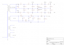

I can't see how it works if you built it as per the schematic. The lower input tube has no signal to it and the grid is grounded via a 100Ω resistor.
Is this supposed to be a balanced line input?
Is this supposed to be a balanced line input?
Yes it is meant for balanced input but basically the input stage is just an ltp sittin atop a constant current source. The lower input tube gets it's signal through the cathode so it works fine.
Joris
Joris
A pentode output and no feedback means you will have high output impedance/low damping factor. Unless your speakers are specifically designed for this unusual scenario you will get a bass peak at the speaker bass resonance and rapidly falling bass below that.
You may also have somewhat high distortion.
Is the CCS circuit correct?
You may also have somewhat high distortion.
Is the CCS circuit correct?
Hi DF96,
Agreed with the pentode no nfb comment. that's why i was thinking about adding that. Just need the figure out how to calculate the appropriate values for feedback from the 16R tap to the negative input on the ltp.
ccs was originally meant for -24vdc supply but otherwise it's straight out of mr Wright's preamp cookbook, sk147 subbed for sk170.
Joris
speakers not designed for this situation btw (sonus faber concertino's)
Unfortunately oscilloscope and function generator are not very efficient tools for fine-tuning the amplifier. Instead you should have distortion meter and audio generator having low THD.
You can add the GNFB without any calculations. Just adjust the output level to, say 1...2 W. Then add some 10k potentiometer from the tap of output transformer to the grid of the LTP. Now adjust the potentiometer and monitor the level of output signal at the same time. When the signal is dropped to half, you have reached 6 dB GNFB etc.
You can add the GNFB without any calculations. Just adjust the output level to, say 1...2 W. Then add some 10k potentiometer from the tap of output transformer to the grid of the LTP. Now adjust the potentiometer and monitor the level of output signal at the same time. When the signal is dropped to half, you have reached 6 dB GNFB etc.
Last edited:
Hi,
Ok so i tried to apply feedback but as soon as i connect it i can actually hear oscillation from the output trannies. I tried 22k, 10k and 3k3.
Could it be i have the output leads reversed? I measured them and they give0.7 and 1 ohms. Right now i use the 0.7 ohm winding for the 8 ohm ls connection and assume the 1 ohm winding to go from the 8 ohm tap to the 16 ohm tap.
any suggestions?
Joris
You may have 8 and 16 mixed up. The 16 ohm extension to the 8 ohm secondary will have 40% more turns but may be thinner wire so more than 40% extra resistance. If your secondary has just three wires then I would assume the 1 ohm section is for 8 ohms and the total winding (1.7 ohms) is for 16 ohms. Or maybe I have misunderstood what you are saying.jazz said:Could it be i have the output leads reversed? I measured them and they give0.7 and 1 ohms. Right now i use the 0.7 ohm winding for the 8 ohm ls connection and assume the 1 ohm winding to go from the 8 ohm tap to the 16 ohm tap.
How, exactly, are you trying to apply feedback?
I tend to agree with DF96, you have mixed up the secondary connections. This could explain why you get oscillations (you are basically applying positive feedback!).
Moreover, as you are using the 8 ohm and 16 ohm taps (i.e. much less secondary turns) your primary load is HUGE! I would guess that if your nominal primary load is 8K with that wrong connection it will be around 50K plate-to-plate. This also explains why you don't have bass (the primary inductance is insufficient). Have you measured the Pout? If my guess is correct your Pout shouldn't be that great....
Moreover, as you are using the 8 ohm and 16 ohm taps (i.e. much less secondary turns) your primary load is HUGE! I would guess that if your nominal primary load is 8K with that wrong connection it will be around 50K plate-to-plate. This also explains why you don't have bass (the primary inductance is insufficient). Have you measured the Pout? If my guess is correct your Pout shouldn't be that great....
Motorboating can be caused by too high amount of GNFB.
How many dB's do you have now ?
Try to begin with some 6 dB only and increase it slowly if necessary.
It is also obvious that you have not connected the secondary correctly, as DF96 wrote.
Then I recommend you to reverse both windings and take the 8 ohms output between 1 ohms winding.
You have added 100 k resistor from the NFB-input to GND. This makes the impedance of NFB-input very high. Originally it was 100 ohms.
My initial idea was that you should keep this 100 ohms connected to GND as in first schematic and connect the NFB-signal via adjustable resistor
directly to the grid.
Last edited:
My guess is that you have simply switched from heavy negative feedback to heavy positive feedback, but I am not too sure which way round it is. You mentioned feedback resistors in the 10's of k region, yet with a 100k to ground you should be using several M's of feedback. Drop the 100k to 1k, then use a 33k feedback. Try both ways round.
Hi,
Ok see the point concerning the input circuitry and feedback implementation i think. I'll lower the input grid resistor to 1K and try some values around 33k for the feedback resistor with the various output connections and see if i can get it working with feedback first.
However I do have balanced sources and preamps (aleph ono clone, d1 dac (diy with tda1541's), pumpkin and an rtp5, all can drive a pretty heavy load i think) so i would like to keep the option for balanced input. So what ballpark would i be in if i used a 47k value for the input grid resistors, something like 500k - 1M for the feedback resistor? I am trying to find a balance between input impedance and noise caused by high resistance values for the feedback resistor i think or is that a misunderstanding of me?
The wire used is just stripped cat5 for the input leads, stranded copper for the connections to the opt's and solid core for the hv and ground lines to the actual circuitry. Got it at the local 'radioshack store' (ie Stuut&Bruin which sadly stopped their business 🙁
Joris
Last edited:
At first, you can not have balanced inputs and GNFB circuit at the same time.
To find the proper amount of GNFB, why don't you just do as I told earlier ?
- have a 100...1k grid to GND resistor first
- connect 1 kHz sine signal to the input
- adjust the output voltage to about middle output power
- add the adjustable NFB-resistor (...100k trimmer) into the circuit
- adjust it until the output voltage is halved
Now you have achieved 6 dB GNFB.
If you wish, you can measure the size of the NFB-resistor and replace it with fixed one.
Hi,
@artosalo. I actually intend to do exactly what you say to get it working first. Basically a combination of what you and DF96 are saying.
What i don't get is your comment about not being able to combine nfb and balanced inputs. I mean like if i look at mr Pass's aleph J, it's input connections and the implementation of feedback it's sort of the same (apart from the output stage of course). Am i really being that stupid?
This is the first time i'm trying to use, mix and match various concepts from others and adapt it to my own personal goals. Not being an engineer (social scientist by education) i'm trying to learn. for example i figured i have preamps with plenty of gain and drive, el84's don't need much drive so i don't need the extra gain provided by the cascode as per the original pp1c thus i simply used an input stage which has a gain of about 10x i think which would make input sensitivity about 1V pp without feedback. Given the amount of gain in the preamps this should allow me to use feedback and get to a situation where about halve of the gain is generated in the poweramp and the rest is controlled by the preamp. Even if i where to make the amp an integrated the 2V standard output of the aleph ono and d1 dac should provide enough signal to drive the amp to max output no?
@DF96, ok yes i can see how the high value feedback resistor would make the circuit more susceptible to stray capacitance (and thus probably stability issues). I don't get the point about the 47k. I see this value and up to 100k - 200k quite often in volume controls for tube amps. I figured the noise issue would be more related to the high value feedback resistor. at least that's what i gathered from the books of mr linsley hood, the higher the resistance the higher the johnson noise.
Regards,
Joris
btw please understand i really appreciate your comments and help. If i question i am trying to learn. 🙂
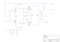
I must correct my comment. Balanced inputs and GNFB can be done.
However this requires essential changes in your circuit.
I understood in the beginning that just bring NFB-signal and one of the signals to the same input as per your schematic.
But now when you referred to Aleph J, I got your point.
With the priciple used below your idea can be realised.
Essential is to use circuitry that gives equal input impedance at both inputs.
Last edited:
Old amps use high values for volume pots. Assuming a low impedance source, the maximum resistance for noise creation is 1/4 of the total and occurs at -6dB volume - probably higher than normally used. At lower volumes you get less noise.
A 47k at your NFB input will be generating the same noise whatever the volume setting.
A 47k at your NFB input will be generating the same noise whatever the volume setting.
- Status
- Not open for further replies.
- Home
- Amplifiers
- Tubes / Valves
- Help wanted with testing and finetuning.