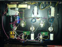
Hi guys, I grafted my diyAudio CCS board to my 300B amp. I replaced the 10K plate resistor with the CCS board (HV PNP CCS) set for 10mA. The cathode bias for the 417A is still an Orange LED.
R1 is set to 22K for ~7mA to fire up the LED.
R2 is set to 100R for 10mA current (1V/10mA), R3 is jumpered.
Transistors are 2N3906 and MJE 350.
417A plate voltage is 127V, from B+ of 143V. Cathode voltage is 1.9V (same as before)
The problem:
I'm getting distorted sound and overloading (cathode LED flashes wildly when signal is fed to the amp)
Where did I go wrong?
Hi,
Katapum
Originally posted by EC8010
I like to be able to swing double the expected swing. You need to swing 45V positive, so 90V of capability would be nice. I suggested 120V because that's probably the amount you need to drop from the HT to your anode voltage, and yes, you need a bit of a margin for the CCS.
Katapum
417A plate voltage is 127V, from B+ of 143V. Cathode voltage is 1.9V (same as before)
Katapum already gave the answer. The 417 plate van swing to a maximum of 143 volts (the B+), well, not even that because there is some loss in the CCS (dropout). So with this stage you can swing a maximum of 20V peak to peak, without clipping.
That's some theory I have started to understand in the last months. Don't know if it is right, if it's wrong I am sure others will correct me!
Erik
That's some theory I have started to understand in the last months. Don't know if it is right, if it's wrong I am sure others will correct me!
You are quite correct. You need at least 100 volts P-P to drive a 300B, and possibly as much as 150 volts. My 5842 - 300B amp uses 375 volts as the plate supply for the CCS that feeds the 5842. I use the same supply that feeds the 300B. The PSRR of the CCS lets you get away with this.
Thanks for all the replies.
I realized it will not be as forgiving as a simple 10K plate load I was eyeing around 150V but thought that 127V is still close to the textbook voltage of 130V (but at 20 something mA). Anyway, my fault.
tubelab, my B+ is 390V and I'm really tempted to be brave as you but isn't it that the max plate voltage of the 5842 is 200V?
The CCS drops just 16V and I will be waaaay over 200V max.
I realized it will not be as forgiving as a simple 10K plate load
I was eyeing around 150V but thought that 127V is still close to the textbook voltage of 130V (but at 20 something mA). Anyway, my fault.tubelab, my B+ is 390V and I'm really tempted to be brave as you but isn't it that the max plate voltage of the 5842 is 200V?
The CCS drops just 16V and I will be waaaay over 200V max.
arnoldc said:Thanks for all the replies.
I realized it will not be as forgiving as a simple 10K plate load
tubelab, my B+ is 390V and I'm really tempted to be brave as you but isn't it that the max plate voltage of the 5842 is 200V?
The CCS drops just 16V and I will be waaaay over 200V max.
orange LED is what really dictates A to C voltage in your circuit (look at tube as on variable resistor,where resistance is dictated with Orange LED - talking in terms of steady state ) ;
you can crank Ub to zillion volts,under condition that your CCS will withstand this voltage-where voltage is in fact difference between Ub and Ua-c ............
I will not dispute Tubelab's bravery,but in this case he 's not brave, just (or JUST) practical 😉
Hi choky, I did take that into consideration when working out on a B+ voltage. Vk=2V + Va=130V = 132V (which I still miss by 5V)
I guess I had a misinterpretation with a CCS in the circuit vis a vis plate load. It seems to be that I will see a horizontal load line instead of the normal angled one with a CCS.
So I'll bump this up and go for 200V Va - 2V Vk = 198V. If I take it direct from B+ of 390V that will be 192V so I just have to worry if the transistors in the CCS can take this?
edit:
On second thought, maybe I should just crank up B+ supply to CCS with reasonable dissipation on the parts.
hehe-=do not be so peeky with voltages ......except when you think about cathode bias voltage;everything else can be certainly in range of +/- 10% and you'll hardly hear the difference....
what I meant- biasing element,in your case Orange Led , will take care about voltage between cathode and anode of tube ...in your case ~ 130V ,if I understood correctly.... ;
so -if you have bias voltage in range of 2V , CCS will burn every excessive and unneeded volt ...no matter if your high voltage supply gives you 200 or 400V........
but-more is better,so just put decent heatsink on MJE and crank it full throttle !
arnoldc said:gotcha!
Thanks again choky!
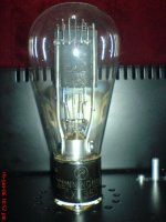
Amp porn added: 😀
now you can send to me all your 10Y/50/300B un-needed toobz for proper disposal

He he he, but I don't think you would ever lust for a pair of cheap generic China-made 300B would you? 😀
arnoldc said:He he he, but I don't think you would ever lust for a pair of cheap generic China-made 300B would you? 😀
cheapskate like me ?
nahhhhhhhhh......😡
GIMME!!!!!!!!!!
just joking .....😉
He he he, but I don't think you would ever lust for a pair of cheap generic China-made 300B would you?
The only ones I use! They are the only ones in my budget.
tubelab, my B+ is 390V and I'm really tempted to be brave as you but isn't it that the max plate voltage of the 5842 is 200V?
When you use a CCS load the plate voltage will be determined by the grid bias voltage. If you have found an LED that gives you 130 volts, it will stay at 130 volts regardless of the plate supply voltage, AS LONG AS THE CURRENT STAYS CONSTANT. Make sure that your CCS can handle the voltage, and then go for it.
My latest amp runs 475 volts, so I put a 10 K 2Watt resistor in series with the CCS to take some of the heat. Drops about 100 volts.
I usually stress test a CCS by shorting the 5842 plate to ground! Do this with the power off, then plug in the amp. This is worst case voltage and dissipation for the CCS. (I use the IXYS 10M45 chip).
Trust me, the 5842 will glow brightly when your CCS shorts out. I found this out while poking around in a live amplifier, and I sparked out the CCS. The 5842 got real red real fast, I yanked the plug, and the tube survived. CCS's are cheaper than 5842's (and a whole lot easier to get) so I would rather blow up a CCS.
I usually stress test a CCS by shorting the 5842 plate to ground! Do this with the power off, then plug in the amp. This is worst case voltage and dissipation for the CCS. (I use the IXYS 10M45 chip).
Trust me, the 5842 will glow brightly when your CCS shorts out.
Oh dear, I think I'll chicken out. May not have the reflexes to turn the amp off. I might be mesmerized by the cherry glow 😀
Oh dear, I think I'll chicken out. May not have the reflexes to turn the amp off. I might be mesmerized by the cherry glow
If it was a 12AT7, ( I have a lot of them) I would just watch it melt. But 5842's are a different story. I still sell amps that use these, and that big box full of them that I once had is looking rather empty.
Ok, it did work now.
From the B+ of 390V, I used a 10K resistor hoping to drop 100V at 10mA (390-290V = 100V/10mA = 10K)
I'm now getting 150V volts at the plate of the 5842 which I think was spot on to what I need. The cathode voltage is 1.8V (which is what it used to be with 10K plate load).
However, I noticed that the voltage drop from the 10K resistor is more than 100V, as the voltage to the CCS is around 238V. While the CCS is set to draw 10mA, it seems to me its drawing more! Somewhere in the region of 15mA.
Why is it so?
The 300B cathode is 61V with 1K3 cathode resistor for around 47mA (my OPT is rated for 50mA, hence the design constraint).
Furthermore, when I swapped in the 50 tube, the 5842 plate voltage became 138V, the cathode voltage remains at 1.8V.
With the 50 tube, the cathode voltage is 55V at 1K3 cathode resistor giving 42.3mA.
Now with lower current on the power section, is the CCS eating up more current now, hence the bigger voltage drop.
Your explanation will be highly appreciated.
On a positive note, it does sound different - tighter low end, more dynamic, and detailed without being aggressive. I thought the mids will become clinical, but thankfully, it did not.
I offer you some tube porn for the help 😀
Attachments
sorry AC
my brain is on red now ;
I will look at your basic schmtc ,but I'm not capable to even find it now.....I'm goin' to ........😴
ps.I'll have wet dreams,tnx to your porn pics
my brain is on red now ;
I will look at your basic schmtc ,but I'm not capable to even find it now.....I'm goin' to ........😴
ps.I'll have wet dreams,tnx to your porn pics
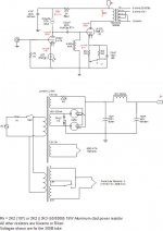
Something there doesn't add up. If you've got a 27k resistor in series with the CCS, at 10mA, you'd expect it to drop 270V... I'd think that a 10k would be more appropriate.

- Status
- Not open for further replies.
- Home
- Amplifiers
- Tubes / Valves
- Help w/ diyAudio CCS implementation