I think you'd clip the stage long before you'd run out of room at the input, though that's not so easy to determine without knowing the B+ voltage. Running super low current, the clipping would be very asymmetrical. Maybe that's what they are after in the first place?
Maybe, but not likely. I think they were just being really safe, and expecting that 'before long' someone would plug a wire harboring mains voltage in the input. As designed, it could take that all day long, and be none-the-worse for the wear. Granted, nothing would come out except a ridiculous clipped hum, but the front end wouldn't pop. ⋅-=≡ GoatGuy ✓ ≡=-⋅
baudouin₀;6081679 said:You would be hard pushed to get 1.2v on a guitar pickup - only when the note is first plucked hard.
Input looks fine to me.
DC block in case somebody plugs in a nasty effects box.
Cap to ground to prevent AM broadcasts getting in.
1MΩ input impedance - correct.
News flash! … modern guitars
[1] have higher output from their passive pickups
[2] almost always have 'direct box' or 'built-in' battery powered preamp
[3] often have a fuzzy string of EFX boxes too
[4] sometimes have synthesizer-pass thru and other devices
Point is (being a hobby-but-active live music tech WITH oscilloscope!) that many a 'guitar' has an output well in excess of ±5 V. I've seen as high as ±10 V in the years I've been doing this. That's why my 'kit' has a few custom socket-plug 10 dB attenuators. If a particular musician's axe is ridiculously hot, I can plug in the attenuator and 'tame' it quite easily. No change in tone either.
Do note that this amp (OP's) does not have an input sensitivity knob/attenuator/rheostat/control. So, having a highly protected input circuit would seem to be most prudent.
⋅-⋅-⋅ Just saying, ⋅-⋅-⋅
⋅-=≡ GoatGuy ✓ ≡=-⋅
Understood but most also come with a volume control.
Anyway modern electric guitar - yuck.
Anyway modern electric guitar - yuck.
Last edited:
baudouin₀;6081704 said:Anyway modern electric guitar - yuck.
Hmmm… the
• sound
• design
• glitziness
• inattention to detail
• overemphasis on faddishness
• promises of magic
• astounding cost
• load of built-in shît
• use of phantom materials
• decline of player talent
• throw-away life-cycles
Just asking… actually. Not trying to start a different debate. ⋅-=≡ GoatGuy ✓ ≡=-⋅• design
• glitziness
• inattention to detail
• overemphasis on faddishness
• promises of magic
• astounding cost
• load of built-in shît
• use of phantom materials
• decline of player talent
• throw-away life-cycles
I have nothing against them actually sorry. I think the more expensive ones do tend to be passive, but you are correct quite often they like to have it set to max. I must admit for recording bass I tend to use a transformer DI box with high impedance on the guitar pickup.
If you wanted a higher input guitar amp you could swap the 12ax7 for 12au7 and adjust the cathode resistors. That would give you a lot lower gain/bigger headroom. I have to say grid blocking is not a good sound and should be avoided -- maybe that is why the mod was suggested so you cannot charge up the DC input cap.a Are the penny has dropped thats why the grid resistor is 68k.
I guess the amp was designed before active pickups were invented.
Last edited:
I have to say grid blocking is not a good sound and should be avoided -- maybe that is why the mod was suggested so you cannot charge up the DC input cap.a Are the penny has dropped thats why the grid resistor is 68k.
I guess the amp was designed before active pickups were invented.
Can you explain what you mean here? Particularly the sound of grid blocking and charging of the DC input cap?
Thank you
Can you explain what you mean here? Particularly the sound of grid blocking and charging of the DC input cap? Thank you
i'm looking forward to the explanation too.
However, as I've come to learn with some quite-precise personal A/B/X testing¹, at least for quality capacitors, capacitors bearing a DC blocking charge do not have any particular 'sound'.
The exception(s) to this are used-to-be-common little brown 'disk' or 'ceramic' capacitors (made from high Z diëlectrics), and an also-once-common-but-now-nearly-extinct-thank-you-God impure-aluminum electrolytic caps. In essence, their nominal capacitance would vary quite a bit depending on the impressed voltage across them.
________________________________________
I'm going out on a limb here, in reading 'between the lines', but I think what Baudouin0 was referring to was the grid current that is sucked into the valve when its grid momentarily 'goes positive relative to the cathode'. This specific condition is to be avoided as much as possible, except possibly for tube guitar amps!
However, I think there is a much simpler explanation for each of the components values.
R₂₇ = protective discharge resistor, for when C₁₅ is carrying a significant DC charge, and the plug is pulled from J₁₀ (the input jack). Note that J₁₀ has internal short-circuiting of the input to ground when a plug is not inserted. When DC is impressed on the C₁₅ (for whatever reason, laudable or criminal, makes no difference), when the ¼" instrument cable is pulled out, the DC needs to discharge somewhere. The 10 kΩ resistor is a safe current-limiting path for that discharge, allowing the poor J₁₀'s shorting contacts not to wear out so rapidly.
R₂₇ also serves as the first level RF-filtering damper, which another poster talked about.
C₂₀ is the “other side” of RF (radio) input filter. Tho' not specified, it ought to be a fairly high voltage device, due to the possibility of the input taking some HUGE A/C voltage hits from extraordinarily badly wired up house wiring. (That goes for C₁₅ too).
The combination of C₂₀ + R₂₇ gives:
Z = 1/(2πFC) … rearranges to
F = 1/(2πCZ), with F=Hz, Z=Ω, C=farads, so
F = 1/(6.28 × 39×10⁻¹² F × 10×10³ Ω)
F = 410,000 Hz
That's the –3 dB corner of the RF filter. All frequencies above that are increasingly attenuated. Of course, 400 kHz is well above any conceivable audio signal. Thus … logic alone makes this an RF filter.F = 1/(2πCZ), with F=Hz, Z=Ω, C=farads, so
F = 1/(6.28 × 39×10⁻¹² F × 10×10³ Ω)
F = 410,000 Hz
R₂₅ (1 MΩ) is the tie-to-ground that gives the 'input impedance' to the amp, as well as that 'leaks' bad-actor DC developing across C₁₅ to allow it to charge up. It is typical for instrument amps to have impedance from 220 kΩ to 1,000 kΩ. This is pretty standard stuff.
R₂₂ is an “aggressive” grid-stop resistor. Grid-stop means “quenches a high-gain valve's desire to oscillate in the radio frequency band”. Necessarily for these little gems do do their job, they need to be attached to the valve socket's grid pin as closely as possible. On circuit boards, no problem. On point-to-point setups, very close indeed. The qualitative “aggressive” means that in normal service, the grid-stop resistor of a 12AX7 stage is usually closer to 1 kΩ to 10 kΩ. However, as this schematic is clearly highly protective of all possible bad-actor inputs and ground loops and everything else, 68 kΩ allows R₂₂ to take full mains voltage if need be, and still protect the poor input valve. Using
P = I E (watts equals volts times amps) and
E = I R (volts equals amps times Ω), then combining them
P = I²R or
P = E²/R
One can see that E = I R (volts equals amps times Ω), then combining them
P = I²R or
P = E²/R
P = (110 VAC)² ÷ 68,000
P = 0.18 W.
Not very high. The amp's front end will survive. The valve won't be happy, but won't burn out.P = 0.18 W.
We've already talked about R₁₂ at 82 kΩ, being a very high value, to set a very low operating current for 12AX7, and to give a bit more gain, the capacitor-bypass of C₃;
R₂ is the 'current-to-voltage' gain realizing anode resitor. The valve ultimately is in charge of 'transconductance', which is to say, varying the current passing thru it in lockstep with the input signal. But the next stage wants 'voltage' on its grid, and so the current needs conversion to voltage. R₂ does that, and along with C₆, the high anode voltage (DC) is blocked, delivering amplified signal to the next stages and sound-shaping network in front of them.
________________________________________
That's all for now.
Hope it helps.
⋅-=≡ GoatGuy ✓ ≡=-⋅
C₂₀ is the “other side” of RF (radio) input filter. Tho' not specified, it ought to be a fairly high voltage device, due to the possibility of the input taking some HUGE A/C voltage hits from extraordinarily badly wired up house wiring. (That goes for C₁₅ too).
C20 is rated at 50VDC and C15 is rated at 250VDC
The qualitative “aggressive” means that in normal service, the grid-stop resistor of a 12AX7 stage is usually closer to 1 kΩ to 10 kΩ...
One of the common "mods" for the JCM800 is to reduce or remove that 68k GS entirely. Some claim that this component is adding fiz and hiss.
I have no intention to remove it or change it, but if there is a tone improvement, i would consider it, because all the amps I am using are studio only, so "protective" is a little less of a concern for my application.
Thank you for that explanation. I read it about 5x and will likely read it 5 more.
OK grid blocking is when the grid starts taking current on the positive cycle of the waveform. This causes the blocking cap to charge up. This then causes the grid to become more negative in bias and eventually biases the valve out of conduction.
Solution small blocking cap and increasing resistor in series with grid. However increasing resistor will increase noise from resistor.
If you look at other gain stages the values of the grid resistors are > 100K to stop this effect.


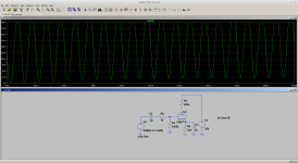
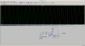
You can see the effect of using 1k instead of 68k the bias shifts. This would be bad as it will effect the decay of the plucked sound in actually blocking the signal in a very bad case if the valve was driven out of conduction.
Solution small blocking cap and increasing resistor in series with grid. However increasing resistor will increase noise from resistor.
If you look at other gain stages the values of the grid resistors are > 100K to stop this effect.


You can see the effect of using 1k instead of 68k the bias shifts. This would be bad as it will effect the decay of the plucked sound in actually blocking the signal in a very bad case if the valve was driven out of conduction.
Last edited:
- Home
- Amplifiers
- Tubes / Valves
- Help Understanding the input circuit on 6505+