Hi folks, hope I am in the right place - Could someone please help me understand all the sections that make up this amplifier and how they all interact? I am trying to learn the basics but cannot find a decent source that explains how amps work of this size / complexity, so any help would be appreciated! Here is the diagram..
Attachments
Hi Charlie
do you have any electronics knolage at all. If not i suggest the first thing to look up and read is Ohms Law. Without that you are you are up a creek without a paddle.
do you have any electronics knolage at all. If not i suggest the first thing to look up and read is Ohms Law. Without that you are you are up a creek without a paddle.
How many years of electricity and electronics theory experience do you have? I think a quick answer to your question would be that a full amp circuit is not a good place to start.
In explaining his amps, Nelson Pass always start with simplified circuit. Your circuit above can also be simplified. But you better read the pdf files of Pass' amps.
What amp is that? It seems that a lot of things has been done to perfect the circuit (so many auxiliary circuits), but imho it doesn't do the necessary things to make a good sounding amp (don't ask me what, because I'm an audio psychic 😀)
What amp is that? It seems that a lot of things has been done to perfect the circuit (so many auxiliary circuits), but imho it doesn't do the necessary things to make a good sounding amp (don't ask me what, because I'm an audio psychic 😀)
Oh not too bad actually, I have a diploma in electronics and understand a *fair* bit, just would like someone to take me through the various stages of the amp so that I can better understand it as a whole entity. I guess it is ok understanding how transistors behave under 'normal' conditions but sometimes I struggle looking at the bigger picture and how everything ties in together, if you know what I mean! E.g. looking at the two transistors grounding the diff pair, are they regulating current and if so how and why do the later stages effect them and the diff amp? Just little things like that really! I am also not entirely sure of the Darlington (mpsa13), is this to maintain stability regardless of temperature?
Charlie,
You chose a complex circuit.
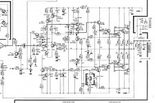
It looks like a commercial PA amplifier.
TR24-27 and TR29-32 comprise a standard Emitter follower output stage.
TR23 is an emitter follower that feeds the output stage. It is loaded by a current source TR28/IC1.
R95 adjusts the bias for the output stage.
IC1 is just an MPSA13 transistor probably mounted to the heatsink for thermal tracking. As the heat builds up, it will vary the current through the current source and thus vary the bias. Normally you would see a "VBE multiplier" doing this duty.
TR17-18 are a "multi-slope VI limiter". This protects the output stage from shorted speaker cables and other severe loads.
TR15-16 are a cascoded voltage amplification stage (VAS).
TR8-9 are a standard "differential input stage" fed by a current source (TR10-11) and loaded by a current mirror (TR7, TR12)
TR6 and TR3 appear to be a "limiter" that removes input signal when amp is cranked too much.
I'm no expert, but I think the designers may have had problems with oscillation, thus they sprinkled lots of compensation capacitors around.
So, this amp may not have sound quality as its first priority.
Regards,
Mike
You chose a complex circuit.
It looks like a commercial PA amplifier.
TR24-27 and TR29-32 comprise a standard Emitter follower output stage.
TR23 is an emitter follower that feeds the output stage. It is loaded by a current source TR28/IC1.
R95 adjusts the bias for the output stage.
IC1 is just an MPSA13 transistor probably mounted to the heatsink for thermal tracking. As the heat builds up, it will vary the current through the current source and thus vary the bias. Normally you would see a "VBE multiplier" doing this duty.
TR17-18 are a "multi-slope VI limiter". This protects the output stage from shorted speaker cables and other severe loads.
TR15-16 are a cascoded voltage amplification stage (VAS).
TR8-9 are a standard "differential input stage" fed by a current source (TR10-11) and loaded by a current mirror (TR7, TR12)
TR6 and TR3 appear to be a "limiter" that removes input signal when amp is cranked too much.
I'm no expert, but I think the designers may have had problems with oscillation, thus they sprinkled lots of compensation capacitors around.
So, this amp may not have sound quality as its first priority.
Regards,
Mike
Download and read read read, Leach's extensive paper on the design and build of his LO Tim amplifier.
Learn to identify the blocks then the circuit makes sense. The primary things to identify here are current mirror, current sources/sinks, Long tailed pair arrangement, and a cascode.
Current mirror - Wikipedia, the free encyclopedia
Current source - Wikipedia, the free encyclopedia
Differential amplifier - Wikipedia, the free encyclopedia
Cascode - Wikipedia, the free encyclopedia
Here's my attempt at a description - hopefully correct 🙂
TR8-TR9 form a "long tailed pair", basically an differential amplifier. TR8's base is the noninverting input, TR9 the inverting input. TR7 and TR12 form a current mirror which equalises the current flowing in TR8/TR9. TR10 and TR11 form a constant current sink which causes a set current to be drawn through the LTP.
TR6 and associated components seem to be a clipping detector - if the amp's input is overdriven, it turns on TR3 and mutes the input.
TR15/16 form a VAS (voltage amplification stage). In this case it is a cascode arrangement, TR15 follows the signal from the LTP, while TR16's base is held at a constant voltage (+V rail voltage minus the 3.3v of the Zener diode). R65/66 act as the current sink for this stage.
TR23/28 are "predriver" stages. TR23 follows the output from the VAS collector, and TR28 acts as a current sink. IC1 is the voltage reference for TR28 and here it is coupled to the heatsink for thermal tracking, to hold a set bias in the output stage and prevent thermal runaway.
TR24-27 and TR29-32 form a Darlington output stage that drives the current into the speaker. The purpose of paralleling many output transistors is to increase current handling capacity.
- Status
- Not open for further replies.
- Home
- Amplifiers
- Solid State
- Help understanding amplifier diagram.