Hi Mooly, thank you so much for your reply.
Unfortunately I'm at a learning curve and I'm not sure which is the bias oscillator...
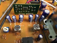
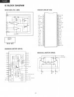
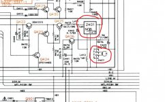
I took measurements of the (what i think it is) the PB Amp outputs. The PB Amp appears to be the small green PCB (Photo 01) as per the diagram (photo 02). It's got a JRC 2068D op-amp on it.
So yes, i found both outputs of the PB Amp (pins 3 and 9) match the frequency signal and voltage I measured at the resistors R105 and R106.
Around 4mV AC RMS and around 96KHz.
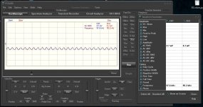
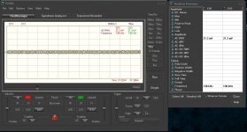
Photo 03 shows the settings of my oscilloscope program while measuring those. Have I set it up correctly in your opinion? (probes set at 1X)
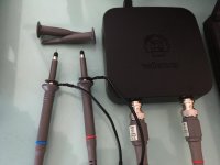
As i was fiddling around with the scope and the measurements, I thought to try taking measurements again without the probe "retractable hook tips". So i removed them (photo 04) and went back to test bias trap at the testing points TP1 and TP2 and by turning the coils to read for any difference (again...)
Guess what?
I was now able to get different readings at the testing points while turning the coils !!!!
It's very low voltage though, going high up to ~2.9mV AC RMS but at this time I was able to set the coils to the lowest reading I could get which was ~1.4mV AC RMS for both channels.
Can you imagine that?
Well, the reason I'm insisting on this Bias thing is that when recording a tape I get some distortion at the playback (but also when monitoring the recorded material by switching from Source to Monitor - it's a 3 head deck).
At this point I will leave the Bias Trap coils at the lowest voltage I could get and focus on the Bias Current and Recording Level adjustments...
P.S. Photo 05 shows the readings i was getting from the other PC scope which i replaced now.
You're right that this one was reading at the TP1 and TP2 bias trap testing points values at the tenths of millivolts and frequency above 100KHz.
But i'm not quite sure if those readings were accurate at all as it was fluctuating a lot from one measurement to the next...
Unfortunately I'm at a learning curve and I'm not sure which is the bias oscillator...
I took measurements of the (what i think it is) the PB Amp outputs. The PB Amp appears to be the small green PCB (Photo 01) as per the diagram (photo 02). It's got a JRC 2068D op-amp on it.
So yes, i found both outputs of the PB Amp (pins 3 and 9) match the frequency signal and voltage I measured at the resistors R105 and R106.
Around 4mV AC RMS and around 96KHz.
Photo 03 shows the settings of my oscilloscope program while measuring those. Have I set it up correctly in your opinion? (probes set at 1X)
As i was fiddling around with the scope and the measurements, I thought to try taking measurements again without the probe "retractable hook tips". So i removed them (photo 04) and went back to test bias trap at the testing points TP1 and TP2 and by turning the coils to read for any difference (again...)
Guess what?
I was now able to get different readings at the testing points while turning the coils !!!!
It's very low voltage though, going high up to ~2.9mV AC RMS but at this time I was able to set the coils to the lowest reading I could get which was ~1.4mV AC RMS for both channels.
Can you imagine that?
Well, the reason I'm insisting on this Bias thing is that when recording a tape I get some distortion at the playback (but also when monitoring the recorded material by switching from Source to Monitor - it's a 3 head deck).
At this point I will leave the Bias Trap coils at the lowest voltage I could get and focus on the Bias Current and Recording Level adjustments...
P.S. Photo 05 shows the readings i was getting from the other PC scope which i replaced now.
You're right that this one was reading at the TP1 and TP2 bias trap testing points values at the tenths of millivolts and frequency above 100KHz.
But i'm not quite sure if those readings were accurate at all as it was fluctuating a lot from one measurement to the next...
Attachments
So it looks like the adjustment is really a kind of 'ultra fine tuning' where the effect is very limited... which is all to the good really as it shows the design is basically well sorted.
Probes (particularly divider probes) can pick up stray radiated fields and that can confuse things.
The JRC 2068 opamp is a good device, very very low noise and ideal for a head amp. It's very like the NE5532 but even better in some aspects of the design.
This is the bias oscillator (another module by the look of it) and the output feeds the erase head and also the Dolby HX Pro processing.
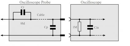
The output of the oscillator will be high, perhaps as much as 30 or 40 volts peak to peak, maybe more, perhaps a bit less... it all depends on the head design. If you measure this then use the divider probe to reduce the amplitude and loading of the scope.
To test your probes for pickup you can try clipping the ground lead to the probe tip (so shorting the probe) and then bring the probe near the oscillator (must be in record mode of course) and see if the scope shows anything.
Anything that registers is being picked up through stray radiation.
http://www.ant-audio.co.uk/Tape_Recording/Library/Bias.pdf
Probes (particularly divider probes) can pick up stray radiated fields and that can confuse things.
The JRC 2068 opamp is a good device, very very low noise and ideal for a head amp. It's very like the NE5532 but even better in some aspects of the design.
This is the bias oscillator (another module by the look of it) and the output feeds the erase head and also the Dolby HX Pro processing.
The output of the oscillator will be high, perhaps as much as 30 or 40 volts peak to peak, maybe more, perhaps a bit less... it all depends on the head design. If you measure this then use the divider probe to reduce the amplitude and loading of the scope.
To test your probes for pickup you can try clipping the ground lead to the probe tip (so shorting the probe) and then bring the probe near the oscillator (must be in record mode of course) and see if the scope shows anything.
Anything that registers is being picked up through stray radiation.
http://www.ant-audio.co.uk/Tape_Recording/Library/Bias.pdf
Attachments
excellent article the one you linked Mooly!
Found the oscillator, is actually on the main board...
If i set the probes to X10 (and the scope too) would that protect the scope from a potential voltage over 30V at the oscillator?
My scope is rated at 30V MAX DC/AC :
oscilloscope specs:
bandwidth: two channels DC to 12 MHz ±3dB
input impedance: 1 Mohm / 30pF
maximum input voltage: 30V (AC + DC)
time base: 0.1µs to 500ms per division
input range: 10mV to 3V/division
input sensitivity: 0.3mV display resolution
record length: 4K samples / channel
sampling frequency: 250Hz to 25MHz
...and you are definitely correct Mooly 🙂
The oscillator measurement gives 32V AC RMS and 98KHz frequency. So i guess no issues there.
Thank you!
The oscillator measurement gives 32V AC RMS and 98KHz frequency. So i guess no issues there.
Thank you!