Hi,
I'm trying to build a Tube PSU for my amp. When I look up some of the electronic articles I find they do not target a novice and more to an expert which I'm not. I want to put a limiting resistor so that I can increase the size of the second cap over 20uF for a 274B tube. The circuit I'm using is from Emission labs circuit #5 (link http://www.emissionlabs.com/datasheets/EML274.htm).
With the first cap at 2.2uf and second at 15uf I get a bit of a hum. nothing changes when the first cap is increased to the max 4uF but when the second is increased to 30uf there is a significant drop and is audible only from a meter away from the speaker. I tried a 47uf first and 100uf second and no hum at all.
The specs say "For a total (C1 + C2) capacitance above 24uF, a limiting series resistor must be used, so the peak in-rush current through the choke is limited to the saturation current of the choke, or max 600mA, whatever comes first. Otherwise tube damage can result. MUST MEASURE. Can not be calculated in a reliable way. For lowest hum, this resistor is in series with the choke. So you get a C-LR-C filter. In this way 200uF is possible."
The saturation current of the choke is 290ma, specs of the tube are on the link above. I'm not sure what is to be measured and how to calculate the resistor value.
Any help is appreciated.
Hi,
I'm trying to build a Tube PSU for my amp. When I look up some of the electronic articles I find they do not target a novice and more to an expert which I'm not. I want to put a limiting resistor so that I can increase the size of the second cap over 20uF for a 274B tube. The circuit I'm using is from Emission labs circuit #5 (link http://www.emissionlabs.com/datasheets/EML274.htm).
With the first cap at 2.2uf and second at 15uf I get a bit of a hum. nothing changes when the first cap is increased to the max 4uF but when the second is increased to 30uf there is a significant drop and is audible only from a meter away from the speaker. I tried a 47uf first and 100uf second and no hum at all.
The specs say "For a total (C1 + C2) capacitance above 24uF, a limiting series resistor must be used, so the peak in-rush current through the choke is limited to the saturation current of the choke, or max 600mA, whatever comes first. Otherwise tube damage can result. MUST MEASURE. Can not be calculated in a reliable way. For lowest hum, this resistor is in series with the choke. So you get a C-LR-C filter. In this way 200uF is possible."
The saturation current of the choke is 290ma, specs of the tube are on the link above. I'm not sure what is to be measured and how to calculate the resistor value.
Any help is appreciated.
It kind of depends on what the power supply is feeding.. You could simulate in-rush current and ripple with various configurations with the program PSUD2 at various amounts of current draw.
You could always add a third node in the power supply.. C-L-C-L-C or something like that. That would allow you to keep a low capacitor value for that first location.
The way I read this, you must observe a max input side capacitance of 4uF regardless. Downstream capacitance may be increased without limit as long as the choke never saturates. Unfortunately, it's not a trivial undertaking to measure surge current in a choke that's elevated a few hundred volts above ground. You could rearrange the circuit to make this more convenient if you weren't using a dual-coil choke. What's needed is a clever substitution for a storage scope with isolated differential probe.
It's not terribly challenging to home-brew a suitable current transformer, and a PC with audio analysis software could do the rest. One way to whomp up a current transformer is to just poke a 'one-turn-primary' wire through the core of an existing audio transformer, and use the existing 'primary' as the CT secondary. If you need more sensitivity, then the existing secondary might be useable as-is. If you have the transformer's datasheet, then you might even be able to avoid calibration in that case. Be aware that CT secondaries must be resistance-terminated.
It's not terribly challenging to home-brew a suitable current transformer, and a PC with audio analysis software could do the rest. One way to whomp up a current transformer is to just poke a 'one-turn-primary' wire through the core of an existing audio transformer, and use the existing 'primary' as the CT secondary. If you need more sensitivity, then the existing secondary might be useable as-is. If you have the transformer's datasheet, then you might even be able to avoid calibration in that case. Be aware that CT secondaries must be resistance-terminated.
All comments above are valid IMHO.
Duncan Amps PSUD II should be able to provide the answers you need and I expect that the 274 is in the library. (The software is free and available for download. Can't provide the link from work unfortunately.)
Ignore the maximum input capacitance at your peril, if the tube does not destroy itself by arcing over during warm up, the excessive charging currents during the time it conducts each half cycle will guarantee a very short service life.
Hi Thehoj,
Thanks for your reply.
The PSU is feeding two 12AU7's and a 5687 per channel on spec 46ma making a total of 92ma @ 300vdc.
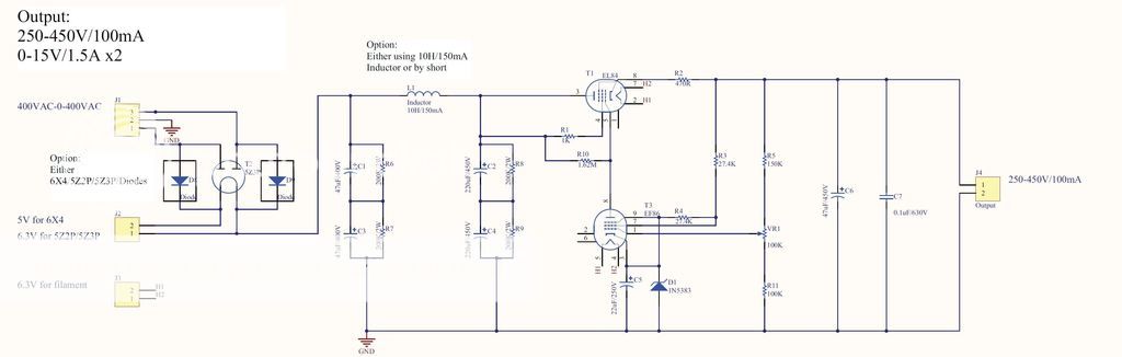
The Circuit I'm using is the following design:
Original - Works no hum but not per tube specs.
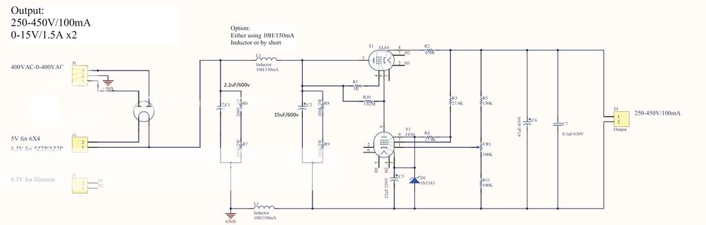
Modified : Within tube specs but noticeable hum. Increasing C2 to 30uf reduces the hum by around 50%.
Once the hum is sorted I will build a second to have independent PSU's for each channel.
Any help is appreciated.
Regards
Thanks for your reply.
The PSU is feeding two 12AU7's and a 5687 per channel on spec 46ma making a total of 92ma @ 300vdc.
The Circuit I'm using is the following design:
Original - Works no hum but not per tube specs.
Modified : Within tube specs but noticeable hum. Increasing C2 to 30uf reduces the hum by around 50%.
Once the hum is sorted I will build a second to have independent PSU's for each channel.
Any help is appreciated.
Regards
Thanks for all your replies. PSUD2 software is helping me get a good understanding of the circuit and its output. Priceless.
Regards,
Regards,
A good active regulation circuit should reduce ripple by at least 40dB (100X). If the regulator does its job properly, then there's no reason for using a tube rectifier and iron core choke. Why not go with SS rectification and CRC filtering? A simple snubber across the transformer secondary eliminates diode switching noise, and the tube regulator delays B+ rise.
This article from AudioXpress 2008 looks like an excellent resource. You might also study the HP 711A manual. I have a couple of those trusty old-timers in my lab and they're excellent.
Is there a more advanced software to PSUD2 which allows a more complex PSU design but is as simple to use as PSUD2?
Perhaps using valve diode with CRC filter is an excellent way for a novice to appreciate what many of the best amps have used for power supplies.When I look up some of the electronic articles I find they do not target a novice and more to an expert which I'm not.
If you can drive PSUD2 to confirm both the hot turn-on peak, and the continuous peak, and the expected rms, and then can confirm by testing the actual rms as well as the noise spectrum that seeps through, then you have made it further than many.
By that stage you may also have a better appreciation of what a regulated supply can achieve, or not.
When you have small filtering capacitors the ripple at the regulator input is maybe so big that the input voltage drops (at ripples negative peaks) below the level where the regulator can work.
You can observe if this is the reason by lowering the output voltage of the regulator with some 50 V.
If the hum disappears then the reason is too small filtering or too low input voltage.
You can observe if this is the reason by lowering the output voltage of the regulator with some 50 V.
If the hum disappears then the reason is too small filtering or too low input voltage.
This article from AudioXpress 2008 looks like an excellent resource. You might also study the HP 711A manual. I have a couple of those trusty old-timers in my lab and they're excellent.
I have been studying the article by Terry Bicknell and thinking of building version 5 of his regulators.
I'm not sure what power rating the resistors should be. 0.5w, 1w or 2w?
R5 specifies 3 watts but what should the others be.
R2, R8 & R10 noted as 82K HS, 470K HS and 470K HS. Are these like 15w/25w resistors with built in Heat Sinks?
The convention in schematics for tube equipment is that resistors are rated at 1/2W unless otherwise notated. Perhaps someone else can comment on the meaning of the "HS" notation. Those resistors certainly aren't high-power doghouse types. There might be some justification for Hand-Selecting R8 and R10 for matching value. That doesn't apply to R2, but maybe it once had a mate at pin 6 of V2?
Why would the designer of the circuit below use capacitors in Series rather than a single cap? I'm looking at if there is a reason other than saving money and space by getting electrolytic caps.
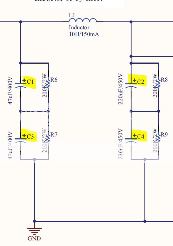
Why would the designer of the circuit below use capacitors in Series rather than a single cap? I'm looking at if there is a reason other than saving money and space by getting electrolytic caps.
FWIW, i use that technique all the time, as a rule of dumb, i use 80% of cap voltage rating, so that with a combined rating of 900v, you can use it as high as
720 volts....
or taken another way, what would my B+ be at if all of the tubes were not plugged in?
FWIW, i use that technique all the time, as a rule of dumb, i use 80% of cap voltage rating, so that with a combined rating of 900v, you can use it as high as
720 volts....
or taken another way, what would my B+ be at if all of the tubes were not plugged in?
Thanks for your reply.
Would it not be better to simply use a single 22uf 1000v film cap instead?
Again its not cost reasons I'm thinking of but B+ quality or final sound quality of the preamp.
- Status
- Not open for further replies.
- Home
- Amplifiers
- Tubes / Valves
- Help - Tube PSU Design