Hello guys,
I have an old cd player from the mid 90´s that, believe it or not, "destroyed" a Marantz SA 7000 KI on several high end setups that it was tested when totally stock (only with an IEC connector and a better power cable).😀😀😀
So it has a great pedigree, so to speak.
It uses a Sanyo transport and DAC (LC7881) and BA15218 Op Amps and cheap components all over. 😱😱😱
Whell, I have two of them, one keeping stock for comparisions and the other already with some light mods as replacing the electrolitic caps with Nichicon Muse and clock mica caps with Soshin Silver 2%.
Now I would like to tinker with the output stage and try tubes 😕😕😕
I have a degree in electronics, but I never really worked as one, so my first hand knowledge is somewhat "rusty", hence this topic asking for ideas on how to proceed with this crazy idea.
Any help will be very much appreciated.
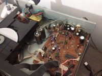
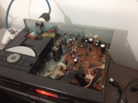
Attached you´ll find the schematics for the player, datasheets on the dac and op amps and also a couple of internal pics.
Regards,
Mauricio
Attachments
The DAC appears to feature a line level voltage output on pins 1 and 20. Meaning, the signal only requires buffering and filtering, but not voltage gain. There are a number of tube buffer kits available if you search, so no need to design and build your own from scratch. You would also need to implement tube power supplies. I would also insert a passive low pass reconstruction filter between the DAC output and the tube stage. Taken together, you may be in for much more bother adding a tube stage than you might at first think.
An alternative would be to 'tweak' the existing op-amp based stages. There are a few simple, but potentially subjectively impactful parts replacements you migh try. For example, replace all the capacitors between the DAC outputs and the RCA jacks with better units, especially those 100nF input coupling units C103, C104 and the 10uF C111, C112 electrolytic output coupling units. The quality of these isn't shown, but I would replace the 100nF with either NP0 type ceramic or metallized polypropylene types.
Replace C111 and C112 with Elna Silmic II. Although, the schematic shows these as polarized they may actually be non-polar types, in which case the polarized Silmics would not be appropriate. Non-polar Black Gate capacitors are the very best sounding electrolytics I know. While now out of production, you might find two new old stock 10uF non-polar units for sale. Obtaining Black Gates would be well worth the search in my oppinion.
In addition, output muting transistors, like Q202 and Q203, are sometimes known for harming the sound. I would simply remove them altogether. While this may permit the occassional chirp or click to be heard when changing tracks and such, but the sound during play may improve.
Last edited:
Great tips Ken. Thanks a bunch.
Almost all electrolytic have already been replaced by Nichicon Muses.
Almost all electrolytic have already been replaced by Nichicon Muses.
If you want an "off the shelf" tube buffer this seller on the auction site is usually very reliable.
HIFI 6J1 Tube Preamplifier Stereo Buffer Preamp Mini Valve & Vacuum Amp J165-19 | eBay
Also look at "Jims Audio"
HIFI 6J1 Tube Preamplifier Stereo Buffer Preamp Mini Valve & Vacuum Amp J165-19 | eBay
Also look at "Jims Audio"
- Status
- Not open for further replies.
- Home
- Source & Line
- Digital Source
- Help - Tube output implementation on an 90´s CD player

