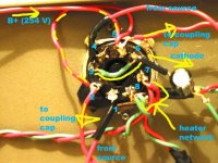
I'm trying to build a simple 6sn7 - 6bq5 se amp using a single 6sn7 dual preamp tube. i built the preamp section but cannot get ANY sound out of it. ...connected to the amp input of a cheap powered computer system or to my headphones. there is no sound whatsoever, not even the hum i would expect from using only capacitative filtering. i have verified the integrity of the solder joints and tried swapping tubes. ...no success. i took out the volume pot and hardwired the source directly to the grid, ...this should give me distorted sound at least, but no success again.
i know the power supply section works, ..delivering 350 V brought down and filtered to 250V B+ for the plate. the cathode is about 10V above ground. I'm sure the high voltage DC gets to the coupling caps just before it is blocked.
with all this in mind, i'm sure i must have done something fundamentally stupid and i appeal to you to help me out or offer hints.
Attachments
You need a plate load. Circuit won't work without it.
Try 30k for Ra and change Rk to 870 which should get you started.
Some basic tube circuit theory would do you the world of benefit.
Study this.
http://www.tubecad.com/articles_2003/Grounded_Cathode_Amplifier/Grounded_Cathode_Amplifier.pdf
Try 30k for Ra and change Rk to 870 which should get you started.
Some basic tube circuit theory would do you the world of benefit.
Study this.
http://www.tubecad.com/articles_2003/Grounded_Cathode_Amplifier/Grounded_Cathode_Amplifier.pdf
If you don't have a plate resistor...then what you have built a voltage to current converter.
A change in the voltage of the grid causes more electrons to flow through the plate causing a change in current! Yep current not voltage.
The simplest current to voltage convertor is a resistor...therefore you need the plate resistor. V=R*I...
Thus the larger the resistance (resistor) the bigger the voltage swing!...try something between 15k and 68k..the lower the resistor value...the most high frequency extention..the higher the resistor...the opposite happens..you get less high frequencies.
Cheers,
Bas
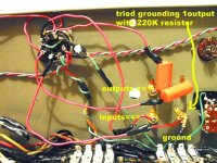
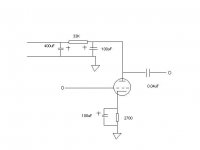
i redrew the circuit with my actual component values and included the power supply voltage dropping resistor (of about 33K value to givea B+ of 2504V). Shouldn't this act as the plate resistor, or is the 100uF smoothing capacitor in the power supply doing something it shouldn't (sending the amplified signal to ground by presenting a lower impedance path)?
I haven't added in a grid resistor. when i had the pot connected, i should have acted like one to ground the input. should i put one back in?
yes, that is a good article on the grounded cathode amplifier, ..i have been reading through it.
thanks
I haven't added in a grid resistor. when i had the pot connected, i should have acted like one to ground the input. should i put one back in?
yes, that is a good article on the grounded cathode amplifier, ..i have been reading through it.
thanks
Attachments
Hi,
Yes.
Disconnect the 100µF cap and you'll have amplification.
The cap across the 33K shunts any AC present on the anode to ground.
Cheers,")
Shouldn't this act as the plate resistor, or is the 100uF smoothing capacitor in the power supply doing something it shouldn't (sending the amplified signal to ground by presenting a lower impedance path)?
Yes.
Disconnect the 100µF cap and you'll have amplification.
The cap across the 33K shunts any AC present on the anode to ground.
Cheers,
Hi,
Not necessarily.
It all depends on how well the PS was filtered already.
Cheers,
Will ripple change?
Not necessarily.
It all depends on how well the PS was filtered already.
Cheers,
yup, fixed, ..sorry i didn't post back earlier. .. thanks all
i dropped the voltage before the 100uF smoothing cap and then used two seperate plate resistors between the dropped voltage and the plate. i'm running at close to 220V on the plate rather than 250V because i don't have the exact valued resistors i need (so i made a mish mash of series parallel resistors to get somewhat close). ..on the other hand, someone mentioned sometime earlier in a somewhat "controversial" 6sn7 thread that starving this tube results in a "sweet" sound, ..can't say for sure yet cos i haven't plugged it into worthy electronics. any comments??
while on the topic, ..any suggestions for a good operating point (i included the 6sn7 chart here) . i was following the tutorial at .boozehond labs but see various references all over the web about suitable operating points. they are using 180V, ..any comments ??
still need to play around with the bias but at least it works. gain is a bit low (need to turn up the volume all the way up to get decent volume .. maybe i'm not pushing enough voltage, ..or maybe i shouldn't expect that much gain from a single 6sn7 working as a stereo driver tube) ..comments ??
more info once i clean up the wiring and finish up the power amp sections and build this into an integrated
fdegrove said:Not necessarily.
It all depends on how well the PS was filtered already.
Now now Frank, let's be realistic, one microvolt divided by a thousand is then only a nanovolt but it's still a fraction of a volt nonetheless...
Tim, your resident pedant

Unless your source puts out any DC you don't need the cap at the input. Sound improvement for less mony, what else do you want.
If you realy need the cap then place it before the volume pot. This way the volume pot is also protected from DC, they don't like any DC current.
If you realy need the cap then place it before the volume pot. This way the volume pot is also protected from DC, they don't like any DC current.
hum solved
managed to obtain a 4H choke . put this in series between the 2 100uF filter caps and the hum is GONE .... TOTALLY.
Another question on this thread, are 2 x 100uF t filter caps oo much to use, .. ie can it be bad for the rectifier (5Y3 ) or any of the other tubes?
thanks
managed to obtain a 4H choke . put this in series between the 2 100uF filter caps and the hum is GONE .... TOTALLY.
Another question on this thread, are 2 x 100uF t filter caps oo much to use, .. ie can it be bad for the rectifier (5Y3 ) or any of the other tubes?
thanks
Hi,
Depends on where you put them...straight behind the rectifier, yes, that'll kill it.
Behind the choke, no, no problem.
The 5Y3GT would take a 20µF cap as an input filter, certainly not more at max. current.
Cheers,
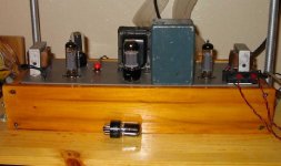
P.S. Nice looking little amp.
Another question on this thread, are 2 x 100uF t filter caps oo much to use, .. ie can it be bad for the rectifier (5Y3 ) or any of the other tubes?
Depends on where you put them...straight behind the rectifier, yes, that'll kill it.
Behind the choke, no, no problem.
The 5Y3GT would take a 20µF cap as an input filter, certainly not more at max. current.
Cheers,
P.S. Nice looking little amp.
- Status
- This old topic is closed. If you want to reopen this topic, contact a moderator using the "Report Post" button.
- Home
- Amplifiers
- Tubes / Valves
- help troubleshooting this diy pre-amp