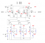
I have put together an equalizer from a schematic, using gyrators.
When I play through it, the sound is very weak and static-y, almost digital sounding. It fizzles away quickly in a distorted mess. If I bypass the EQ, the sound is back and massive. There is also a low end hum with the EQ in. The three frequency controls do have an effect on the output. They all contribute to their corresponding frequency ranges. The low pot accentuates the hum as well.
So far, I have swapped out all the transistors, re-soldered the inputs/outputs, replaces the input/output coupling capacitors, tested all the transistors (diode check), resistances all look good from measuring in circuit. I have combed over the schematic vs layout three times now.
I am running out of ideas other than starting from scratch. Any ideas?
Attachments
Hi
Q1 is being used as an emitter follower and they are prone to oscillation particularly if you are using the mpsa63 (high gain darlington) . Try putting a 3K3 resistor in series with the base of Q1
Q1 is being used as an emitter follower and they are prone to oscillation particularly if you are using the mpsa63 (high gain darlington) . Try putting a 3K3 resistor in series with the base of Q1
The circuit is drawn as positive earth. The 26 volts rail should be minus 26 and all other voltages should be negative.
Have you wired the power supply up correctly with positive to ground ?
Have you wired the power supply up correctly with positive to ground ?
Thanks, I have replaced the mpsa 63 for 2n2907, and mpsa20 for 2n2222. The circuit works perfectly now, other than a bit of distortion at max tone settings. I meant to write the Vcc as negative but forgot.
Thanks again! 🙂
Thanks again! 🙂
Glad you have the circuit working now, however by changing to a lower DC current gain transistor you will have compromised the voltage divider formed by R227+R262 and R392 and it will no longer be determining the voltage at the base of Q1 and subsequently the whole of the voltage operating point right up to the output . Q1 and its load will be choosing its own base voltage which could now be -ve 1V and may be the reason you are getting distortion.
Last edited:
- Status
- Not open for further replies.
