For the life of me, I can't seem to figure out what the issue is...
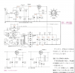
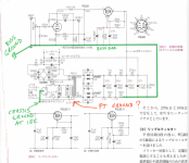
I found a schematic and article (in Japanese) for a PCL83 line amp. I had most of the parts and the tubes and transformer were relatively cheap. I mocked it up in the chassis, no smoke or anything, the power supply is close to what is specified at it's test points heater is 12.6V and the rest are a touch higher than as spec'd; however, the test points in the audio circuit are way off and I can't seem to figure out how to diagnosis the issue. Specifically, Pin 1 (81.4V) is measuring about 220V and Pin 3 (2.9V) is also measuring about 220V!
The other test points on the pentode side of the PCL83 are high, with Pin 8 (312V) measuring 350V and Pin 9 (193V) measuring 205V.
I've gone over the layout and values over and over, yet can't track down the problem.
On a side note, functionally the preamp is passing signal with and without power; however, as hooked up to a junky amp there is severe attenuation as compared to the source placed directly in line with the amplifier.
This is my first build from a schematic and while I've learned a lot, I've reached the limits of my abilities. Thanks in advance for any help or suggestions.
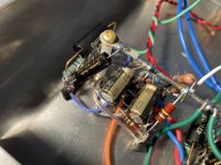
I've attached the schematic and pics of the build with details of one channel.
I found a schematic and article (in Japanese) for a PCL83 line amp. I had most of the parts and the tubes and transformer were relatively cheap. I mocked it up in the chassis, no smoke or anything, the power supply is close to what is specified at it's test points heater is 12.6V and the rest are a touch higher than as spec'd; however, the test points in the audio circuit are way off and I can't seem to figure out how to diagnosis the issue. Specifically, Pin 1 (81.4V) is measuring about 220V and Pin 3 (2.9V) is also measuring about 220V!
The other test points on the pentode side of the PCL83 are high, with Pin 8 (312V) measuring 350V and Pin 9 (193V) measuring 205V.
I've gone over the layout and values over and over, yet can't track down the problem.
On a side note, functionally the preamp is passing signal with and without power; however, as hooked up to a junky amp there is severe attenuation as compared to the source placed directly in line with the amplifier.
This is my first build from a schematic and while I've learned a lot, I've reached the limits of my abilities. Thanks in advance for any help or suggestions.
I've attached the schematic and pics of the build with details of one channel.
Attachments
-
 Screen Shot 2023-01-18 at 11.30.01 AM.png683.4 KB · Views: 269
 -
 IMG_3806.JPG434.5 KB · Views: 221
 -
 IMG_3807.JPG369.3 KB · Views: 152
 -
 IMG_3808.JPG364.6 KB · Views: 154
 -
 IMG_3809.JPG429.3 KB · Views: 149
 -
 IMG_3810.JPG394.3 KB · Views: 156
 -
 IMG_3813.JPG531.5 KB · Views: 158
 -
 IMG_3805.JPG387.1 KB · Views: 224
Last edited:
Hmmm... I dont see a short in the layout, but again maybe I'm missing it. Are you seeing something I don't? No continuity betweens Pins 1 and 3 on the tubes.Pin 1 and pin 3 are shorted?
Jan
Two pins with the same voltage have a great chance to be shorted. Did you measure resistance between them?Hmmm... I dont see a short in the layout, but again maybe I'm missing it. Are you seeing something I don't? No continuity betweens Pins 1 and 3 on the tubes.
Not just the tubes, but in the circuit.
Jan
The resistor on pin 3 to gnd has at least one yellow stripe, so it can't be 620 ohm.
It looks like blue-red-black-yellow--brown, that would be 6,200,000 ohm 1% or 6.2 Megohm ... it should be blue-red-black-black--brown ...
It looks like blue-red-black-yellow--brown, that would be 6,200,000 ohm 1% or 6.2 Megohm ... it should be blue-red-black-black--brown ...
Last edited:
That's one alternative. The other is that NO current is flowing and everything is floating-up to the supply.Two pins with the same voltage have a great chance to be shorted.
As said, a loose of bogus cathode resistor will do that.
Also a stone-cold heater. We are told that there is 12V around but I have been fooled by an un-hot heater. (Gets real tough for intermittent heater in metal tube on hot chassis.) I guess the fact the triode has 220V suggests the pentode has power, and both in the same bottle suggests..

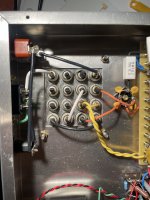
I was wondering if you had got your g1s and the g2 mixed up on the socket. It isa shame they are obscured with those caps
Thank you so much for all of your help and insight. Went through it with a fine tooth comb, double and triple checked everything yet as @pwgtang suggested and @Sorento spotted, I had misread the resistor on my meter and had a 620K ohm cathode resistor instead of a 620 ohm. Should have triple checked the stripes. Hard lesson to learn. Ugh.
The preamp is now passing sound and acting as designed except for an audible 120Hz "buzz" signalling a ground loop somewhere in the circuit. I feel that my grounding strategy is sound, but would love another set of eyes on it.
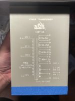
Because I'm using a different power transformer (PT) than was specified - took a little configuring but voltages are good - I wonder if this might be the root of the issue. I'm using the center tap (CT) and one leg of the 260V secondary as opposed to both legs for 520V, and have the 5V, 6V and 6.3V secondaries in series to get my B+ to 17.3V before the rectifier. Am I missing a ground on the power transformer? I've never used a big sealed PT before... Does the case need a seperate ground? Somewhere I was reading about center taps being grounded but I'm not sure I fully understand when this would be implemented.
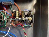
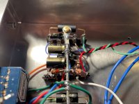
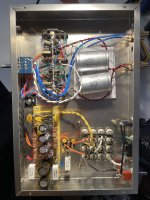
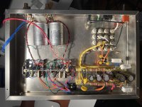
I've attached images of the preamp internals, details of the PT and the grounding scheme.
Again, any help getting this to the "finish line" would be so appreciated. Thanks!
The preamp is now passing sound and acting as designed except for an audible 120Hz "buzz" signalling a ground loop somewhere in the circuit. I feel that my grounding strategy is sound, but would love another set of eyes on it.
Because I'm using a different power transformer (PT) than was specified - took a little configuring but voltages are good - I wonder if this might be the root of the issue. I'm using the center tap (CT) and one leg of the 260V secondary as opposed to both legs for 520V, and have the 5V, 6V and 6.3V secondaries in series to get my B+ to 17.3V before the rectifier. Am I missing a ground on the power transformer? I've never used a big sealed PT before... Does the case need a seperate ground? Somewhere I was reading about center taps being grounded but I'm not sure I fully understand when this would be implemented.
I've attached images of the preamp internals, details of the PT and the grounding scheme.
Again, any help getting this to the "finish line" would be so appreciated. Thanks!
Attachments
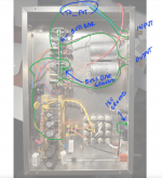
I think the ground is at the wrong end of your bus. Should be at the -VE of the last 2nd filter cap, or after that second resister maybe.
Thanks but could you please clarify? RIght now the bus bar is grounded from the center between the two channels to a single solder tag. Do you mean to move it to the end of the bus bar near the caps? Seems like diagnosing these things is like alchemy.I think the ground is at the wrong end of your bus. Should be at the -VE of the last 2nd filter cap, or after that second resister maybe.
The idea is that the PSU is grounded after the main smoothing of the supply (usually second smoothing cap), and then the other stages are grounded back to that point in the order of descending sensitivity to PSU noise, so that they are isolated as much as possible from the PSU. There is a sticky thread all about grounding, and it is a bit of a science to get right.
Aiken amps - Grounding
Aiken amps - Grounding
...Better yet is a two-point star, where the main the power grounds (PT center tap, first filter cap ground) and output stage grounds (output tube cathodes for fixed bias, or cathode resistors for cathode biased, and output transformer secondary ground) are connected together at a single point, right at the ground of the first filter capacitor. The ground of the second filter capacitor, after the choke or filter resistor, is the star ground point for the preamp stage grounds. Use a local common point for each preamp stage ground, and run a wire from this common point back to the second star point. If two stages are out of phase with each other, they can share a common local ground, but don't use more than two stages per local common ground. Connect the star ground points together with a wire, and use only one connection to the chassis. ...
The transformer looks good, you can try to open the ICE to chassis ground connection to see if the hum disappear.
Thanks for the help as always. Will sit down with both articles this evening!
@OldHector Regarding the quote:
"...Better yet is a two-point star, where the main the power grounds (PT center tap, first filter cap ground) and output stage grounds (output tube cathodes for fixed bias, or cathode resistors for cathode biased, and output transformer secondary ground) are connected together at a single point, right at the ground of the first filter capacitor."
In my instance where Im using one leg of the CT secondary for 260V - as opposed to both for 520V - should I be running the 0V CT to ground with filter caps etc.?
And yet this is a very popular lesson!!! Everybody does it all the time. With repetition we learn to check for lost zeros a little sooner every time.620K ohm ...instead of a 620 ohm. ....Hard lesson to learn. Ugh.
Why do you say "ground loop"?an audible 120Hz "buzz"
The problem is those bright yellow wires heading straight for the audio circuitry before veering to the rectifier. The primary rectifier circuit is full of snakes. 100/120Hs buzz-snakes.
Keep that circuit WAY away from your precious children and audio. The whole power board could be turned-around so the dirty yellow wires hug the chassis and the preamp is nearest the clean filtered DC end of the strips. (Yes, twisting helps but is not enough.)
Last edited:
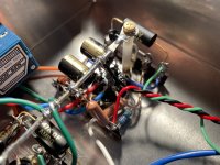
So I flipped the power supply board, read the Aitken Amp article, put in my DIY stepped attenuator, cleaned up some connections while I had it in pieces, and... VOILA! Dead quiet!And yet this is a very popular lesson!!! Everybody does it all the time. With repetition we learn to check for lost zeros a little sooner every time.
Why do you say "ground loop"?
The problem is those bright yellow wires heading straight for the audio circuitry before veering to the rectifier. The primary rectifier circuit is full of snakes. 100/120Hs buzz-snakes.
I imagine it is a sum of the parts but I thought I'd share a pic of the amp after the changes before powering up - note: the ground wire was tied to the chassis between the tubes.
Thanks all for your help. Lots more to learn about ground loops, etc. but I appreciate your time and expertise.
Attachments

- Home
- Amplifiers
- Tubes / Valves
- Help troubleshooting a PCL83 Line Amp