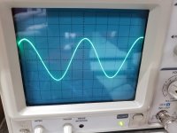
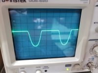
I have a left channel distortion caused by my hand slip. The signal looks good going into the amp circuit, 1khz sine wave. At Q701 (2SA798) it starts to distort. I replaced the 2SA798 with one I got from eBay and it may be bad. I pulled all of the other transistors in the circuit and they check ok using the diode and hFE functions on my meter. I was a licensed tech 40 years ago but it is really just a hobby now.
Here are photos of the scope readout and that part of the schematic.
This is PIN 1, 200mv

PIN 2, 2.8v

PIN 3, 130mv

PIN 4, 2.7v

PIN 5, 130mv

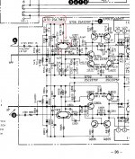
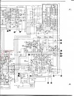
SCHEMATIC with numbers, "A" is the left input from the preamp.

Here are photos of the scope readout and that part of the schematic.
This is PIN 1, 200mv
PIN 2, 2.8v
PIN 3, 130mv
PIN 4, 2.7v
PIN 5, 130mv
SCHEMATIC with numbers, "A" is the left input from the preamp.
Attachments

Last edited:
Can you measure the quiescent DC voltages on Q701 C B E?
In Canada:
2SA798 - Transistor PNP - SP9 - NTE 43 - Addison Electronique
https://www.nteinc.com/specs/10to99/pdf/nte42_43.pdf
In Canada:
2SA798 - Transistor PNP - SP9 - NTE 43 - Addison Electronique
https://www.nteinc.com/specs/10to99/pdf/nte42_43.pdf
Last edited:
Can you measure the quiescent DC voltages on Q701 C B E?
pin 1 - B 49mv
pin 2 -C -35.3v
pin 3 - E .647v
pin 4 - C -35.3
pim 5 - B - 51mv
Thanks
Looks ok since both sides are similar, could be another part in the circuit.
Can you check the DC voltages in the next stage, Q702, 703, 704, 705, 706?
Can you check the DC voltages in the next stage, Q702, 703, 704, 705, 706?
Last edited:
Looks ok since both sides are similar, could be another part in the circuit.
Can you check the DC voltages in the next stage, Q702, 703, 704, 705, 706?
B C E
Q702 -35v / -.66v / -36v
Q703 -35v / -1.1v / -36v
Q704 0v / 38v / 0.63v
Q705 38v / 1.7v / 39v
Q706 38v / 38v / 39v
I noticed that the voltage on the collector of Q701 should be -44.7, so it is a little low.
I checked the STK-0050
pin 1 - -.78v should be -1.2
pin 2 - -43.7 ok
pin 3 - 4mv ok
pin 8 - .629v should be 0
pin 9 - 43.7v ok
pin 10 - 1.68v should be 1.2
Last edited:
Nothing is really off, other than the -35V being 10V too low. Maybe the STK is drawing too much current.
Try comparing all these DC voltages with the good channel. The -35V is shared though.
Try comparing all these DC voltages with the good channel. The -35V is shared though.
Nothing is really off, other than the -35V being 10V too low. Maybe the STK is drawing too much current.
Try comparing all these DC voltages with the good channel. The -35V is shared though.
I did check the STK in the other channel and the voltages are spot on.
The left 2SA798 (Q801) and other transistors were also around 39v but the sine wave is perfect, no clipping. It may be the STK.
Here is what happened:
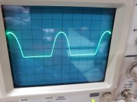
I built 2 discreet versions of the STK-0050, I installed one in the left channel to test it, the STK-0050 was working OK. My dumb *** put a wire too close to a bolt and blew the discreet version. I put the original STK back in and the left channel was dead. I found two transistors Q707, 708 that were bad so I replaced them, it worked but started getting distortion and the sine wave was clipping. I thought the 2SA798 was bad because the sinewave started clipping there. I still have another discreet STK I think I will put that in and test it.
Attachments
You damaged the STK.
Now you need to find a replacement, or put other chip amps higher up on the heat sink, and wire them up.
The STK is really two mono amps with a common power supply in the same housing.
So yes you can put two, one for each channel.
Also, the damaged one may fail, taking speakers and transformer with it.
Take care.
You damaged the STK.
Now you need to find a replacement, or put other chip amps higher up on the heat sink, and wire them up.
The STK is really two mono amps with a common power supply in the same housing.
So yes you can put two, one for each channel.
Also, the damaged one may fail, taking speakers and transformer with it.
Take care.
Yeah you are probably correct. I have another STK made from discreet components. I am going to put it in and test it.
Thanks
You damaged the STK.
Now you need to find a replacement, or put other chip amps higher up on the heat sink, and wire them up.
The STK is really two mono amps with a common power supply in the same housing.
So yes you can put two, one for each channel.
Also, the damaged one may fail, taking speakers and transformer with it.
Take care.
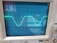
I replaced the STK with the discreet version I made and it is still clipping. I get the exact same voltages and scope readings as I did with the original STK.
Ok, unplug the AC power, and in-circuit diode test all diodes and transistors (forward and reverse).
Compare the readings to the good channel.
Compare the readings to the good channel.
Ok, unplug the AC power, and in-circuit diode test all diodes and transistors (forward and reverse).
Compare the readings to the good channel.
I have to go to work but will do that later. Thanks.
- Home
- Amplifiers
- Solid State
- Help trouble shooting Sanyo Plus 55