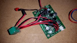
I am trying to replace the stock pot on my YDA-148 Class D amp with a pot that will also switch power. The stock one and replacement both say 50k. I basically just matched the 6 holes on the board with the posts on the pot exactly as they were originally. I then ran the 12v+ in line through the back 2 posts on the new pot. Power switching and the right channel work perfectly with volume control. The left channel, however, does not. The left channel is just barely audible at full volume. Thinking my replacement pot was faulty, I pulled another identical one off of another functioning amp and wired it identically with the same result.
Am I wiring something wrong? Does an 8 post power switching pot have a different pin configuration than a standard 6 pin? I had previously run the amp several times with the original pot and both channels output fine.Thanks.
Am I wiring something wrong? Does an 8 post power switching pot have a different pin configuration than a standard 6 pin? I had previously run the amp several times with the original pot and both channels output fine.Thanks.
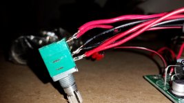
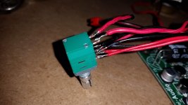
Well without pictures I'm not going to commit to saying they are the same but typically yes, they are. Centre pin is wiper. Impossible with just this info to say what has gone wrong. Maybe post some pics of the pots (original and replacement) and the amp showing where /how it is fitted.
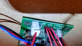
So its one channel not working following replacing the control. Hmmm, pins outs will be the same. I would be looking carefully for any damaged or broken print around the volume control connections on the PCB. If its a "double sided board" (PCB tracks both sides) then make sure there is continuity from top to bottom at those soldered connections. Also check for inadvertent solder splashes where a blob of slolder may have fallen from the iron onto the board shorting something out.
So its one channel not working following replacing the control. Hmmm, pins outs will be the same. I would be looking carefully
for any damaged or broken print around the volume control connections on the PCB.
Also, try swapping channels at the pot terminals.
Thanks. I have replaced the pot at the ends of the jumpers and the result is identical (a just barely audible left channel). My problem must be at the PCB level whether it is a bad solder job or I have shorted something. Maybe Ill try it with another board. Ill report back.

- Status
- Not open for further replies.
- Home
- Amplifiers
- Class D
- Help: Trouble Replacing Potentiometer