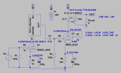
I also planning to remove the one of the 200R resistor from the 2x200R and put a bypass capacitor in the place. It's an easy change.
I really think you should use a cathode by-pass cap like I suggested. 🙂
If you remove one of the 220ohm cathode resistors, your bias will change. I am a bit confused as in post #1 you state that with 2x 220ohm cathode resistors (in parallel, so equivalent to 110ohms) you have a cathode voltage of 5.18v -> This would result in a 47mA quiescent operating point.
However in post #9 you seem to be suggesting that the quiescent operating point is at 28mA (= significantly less power). Now, if you use just one 220ohm cathode resistor and hope for around 28mA quiescent operating point, the bias (cathode voltage) should be 6.16v...
Sorry for complaining that the numbers don't seem to match very well.
From my perspective, having a bit too much power is never a problem. You can use lovely things like feedback to reduce power and improve PSRR... 😉
One possibel solution can be a regulate power, simply circuitThe power supply question is difficult
just an example
This is for a preamp but changin the 100 ohm and 1 kohm resistors and the zener you can use the 300 Vac easily to reach 280-300 Vdc that is you need
And you can made it on a proto card.
The ripple is gone.
I think you don't need the use of some gyrator or other sand circuit.
Change the input resistor to 50 kohm max. And set the 88 bias to 8-10 mA
Agree about the bypass of the 84 cathode.
Hi, thank you 🙂 I didn’t read the forum, just now, I was busy with modification, and I ended up almost the same solution 😀
Tomorrow will be the listening session
I use a similar PSU circuit, with the following main differences:
- R4 is lower in value, set to have 2 mA on the zeners D1 and D2;
- a resistor is addes between R4 and C2 to have a RC of around 20 seconds to have a softstart and further noise reduction;
- a TO247 mosfet with a huge SOA instead of the IRF820, and at least 15-20 V more are needed upstream;
- No RCRC after the regulator, just two 10 Ohm resistors and a capacitor for each channel (plus another with 1/100 of its value) and that’s it.
- For a triode is enough a simple ccs, no need for a gyrator;
- The resistor at the cathode of the driver must have a lower value to reach around 10 mA;
- Keep the possibility to try the UL plus Schade (plus cathode) feedback: you may find to like it more than triode mode.
According to Hitchhikers Guide to the Galaxy, it was because the colour was not right.Why do we have to reinvent the wheel?
I have found that, in contrast to other models, the models made by Ayumi Nakabayashi do model grid current realisticly. Try his model forYou can model grid current in LTSpice by putting a diode from grid to cathode of the EL84.
6BQ5/EL84. You can find them here: https://www.diyaudio.com/community/threads/vacuum-tube-spice-models.243950/#post3662623
- Home
- Amplifiers
- Tubes / Valves
- Help to understand why EL84 SE amp clipping
