Hello, I need some help to understand why my amp is clipping.
When the input signal bigger than 330mV rms, the lower half wave start to clipping. If I increased the input signal then the upper half wave start to clip. I was not able to reproduce the lower half wave clipping in LTSpice, but exist in the real amp.
I would like to know what causing the lower half wave clipping, and what causing the upper half wave clipping.
I tested the following: I pulled out the EL84 output tubes, so only the ECC88 was in, then I put the scope probe to the coupling capacitor leg, no cipping after the ECC88.
When I put the EL84 back (scope probe not changed) the lower half wave clipped after ECC88.
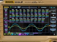
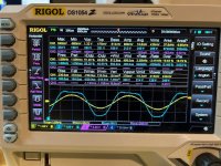
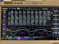
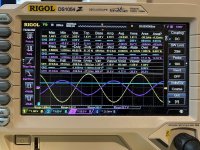
The simulation shows the Anode voltage of the EL84 output tube.
The pictures shows same Anode voltage of the EL84 output tube.

Any idea?
The output transformer is Toroidy (link)
When the input signal bigger than 330mV rms, the lower half wave start to clipping. If I increased the input signal then the upper half wave start to clip. I was not able to reproduce the lower half wave clipping in LTSpice, but exist in the real amp.
I would like to know what causing the lower half wave clipping, and what causing the upper half wave clipping.
I tested the following: I pulled out the EL84 output tubes, so only the ECC88 was in, then I put the scope probe to the coupling capacitor leg, no cipping after the ECC88.
When I put the EL84 back (scope probe not changed) the lower half wave clipped after ECC88.
The simulation shows the Anode voltage of the EL84 output tube.
The pictures shows same Anode voltage of the EL84 output tube.
Any idea?
The output transformer is Toroidy (link)
Attachments
There is too high ac-voltage at the g1 of EL84. G1 to cathode (bias) voltage is - 5.2 Vdc, so the clipping start when ac-signal at g1 of EL84 exceed some 11...12 Vpp, i.e. some 4 Vrms. So 330 mV at the grid of ECC88 is too much.
The EL84 will clip on one side due to the grid being overdriven, causing it to draw grid current. It will clip on the other side due to cut-off. You can model grid current in LTSpice by putting a diode from grid to cathode of the EL84.I was not able to reproduce the lower half wave clipping in LTSpice, but exist in the real amp.
Yellow - Input signal ; Blue - EL84 Anode ; Magenta - after coupling capacitor of ECC88 stage


So if I understand it correctly, the red marked clipping caused by the overdirve? And what is the green marked "sharp" clipping
And why the output signal of the ECC88 influenced by the EL84? I mean there was no clipping if the EL84 was not installed, but started to clip when EL84 was in place at the same input signal level?
Sorry, but I have some gap in my knowledge, and I would like to understand what's going on.
I also realized that the R8 330k resistor lifting the signal after the coupling capacitor (relative to the ground) so the signal is asymmetric to the 0V
Attachments

When the EL84 grid is driven above its cathode voltage, the grid becomes forward biased -electrons become attracted to the grid. There is a hidden diode inside the EL84 between grid and cathode.
Designing a single-ended vacuum tube amplifier is a bit of a balancing act. If you don't have a full understanding, then I would suggest obtaining at least something like the old RCA RC-30 tube manual. It has a section in the front on how to use plate curves to draw a load line on how to match a transformer impedance for a single-ended amplifier. It will go into a reasonable amount of detail and worth reading.
In short, I would suggest the design starts with the output stage, i.e., the final power tube (EL84 in your case) and the output transformer. The balancing act mainly starts here. The goal is to have the output transformer matched well against the output tube and the voltage and current lines of operation. This simply means plate voltage, cathode current and grid bias voltage. Then you have the grid being driven positive and negative which increases or decreases current flow. This is what controls the voltage change in the output transformer primary. The design needs to find the center spot in the operating parameters of the output tube, so you optimize the overall performance.
Some of the issues you can end up with concerning the grid drive are:
1 - Driving the grid negative to the point where the output tube goes into cutoff, i.e., it's no longer conducting. If this happens, there's no current flowing in the output transformer primary, so zero signal exists.
2- Driving the grid positive to the point where it exceeds the voltage potential of the cathode. Once this happens, the grid draws current and puts a different load on the driving stage. This is the difference between Class A1 and Class A2. You need a different driver stage for Class A2 operation (your circuit will not suffice).
3- Driving the grid positive where either the tube saturates, i.e., it can't conduct any harder, OR, the transformer core has become saturated magnetically and you can't drive any higher signal level.
All of the above result in either clipping at high current or dropout at no current. Looking at your circuit, several points become obvious:
1- Your working grid voltage is far too low. You can barely drive 10 volts peak-to peak before the grid goes positive and perhaps the tube goes into cutoff at the negative end.
2- Your plate voltage is on the low side for driving a 5K primary impedance.
3- Your cathode current versus plate voltage and grid voltage don't give you much room to work per plate curves.
As you're running the EL84 in triode mode, you can only expect barely 2-watts of output power. Also, the standard datasheet shows a 3.5K load impedance, a 250-volt plate supply and a 270 ohm cathode bias resistor. Cathode current is within the range of 34-36 ma. This works out just over 9 volts of grid bias. I suggest you start with these operating parameters and look at making some changes to see if you can get better performance with the referenced 5K load impedance. You'll need to increase the plate voltage supply and reduce the cathode current (which will increase the grid bias voltage) and you might get a bit more power from the output stage.
The driver stage needs to be able to drive a larger peak-to-peak signal cleanly than what the output tube can handle. In Class A1 operation, this is basically twice the grid bias voltage.
Again, I recommend you do some reading from the RC-30 manual (PDF copies exist online) and get familiar with how this works.
Good luck, have fun!
Well, any 6BQ5/EL84 datasheet tells us something else...The EL84 plate voltage should be 315v, not 215v. Remove 1 cathode resistor.
To the TO: You observe a typical behaviour of any SE class A amplifier with a pentode. Guess why datasheets for any power tube relate the power output number in SE class A operation to a THD of a whopping 10%? (Answer: Tube manufacturers alway have been trying to squeeze out as much as possible of their products.)
Best regards!
Thank you for all.
I have read more about it, and please correct my theory if it's failed.
I used the loadline calulator:
Universal Loadline Calculator

The Slope of the Loadline determined by the Output Transformer (I already have it) 5k:8Ohm
Point A is the maximum plate current, according to the datasheet 48mA let's say 50mA
Point C is the maximum plate voltage according to the datasheet 300V
Point B is the operating point in the middle between A and C
So based on the graph 215V and 28mA should optimum. I guess
Is that theory correct?
I have read more about it, and please correct my theory if it's failed.
I used the loadline calulator:
Universal Loadline Calculator
The Slope of the Loadline determined by the Output Transformer (I already have it) 5k:8Ohm
Point A is the maximum plate current, according to the datasheet 48mA let's say 50mA
Point C is the maximum plate voltage according to the datasheet 300V
Point B is the operating point in the middle between A and C
So based on the graph 215V and 28mA should optimum. I guess
Is that theory correct?
Yes, but because you have cathode bias, you should subtract the cathode voltage to figure your plate voltage point. So, if you are restricted to only 215v for a supply voltage than you won't get the most power the EL84 can give you. You are well under the best Class A power dissipation that would be closer to 12W on the plate. I estimate you can create about 1.5W of signal power at the EL84 plate and a final output power of 1W with your triode configuration.
Yes, my Loadline is far away from max power hyperbole. I just want to be sure that increasing the plate voltage, or increasing the plate current will not give better solutions since the slope is predefined.
Did you check the driver output signal with the EL84 in place? When you pulled the EL84 and the signal stopped clipping, it was because your voltage of B+ jumped higher without the output tube load on the B+. It likely changed the operating point of the driver. Is your PS transformer too small for normal circuits of this type?
The load line shows the quiescent (DC) operating point at 215v/28mA, but the circuit diagram and voltages show it's 220v/47mA.
The circuit diagram shows no bypass capacitor across the cathode bias resistor, but the load line graph assumes the (AC, i.e. signal) bias network has zero impedance. It's important to distinguish the AC operating point from the DC operating point.
I hope that helps!
The circuit diagram shows no bypass capacitor across the cathode bias resistor, but the load line graph assumes the (AC, i.e. signal) bias network has zero impedance. It's important to distinguish the AC operating point from the DC operating point.
I hope that helps!
Thanks for the suggestion. I also realized, without the load of the EL84 tubes the raw DC voltage was higher. But I'm using a regulated voltage for ECC88, so the increased raw DC not increasing the plate votage of the ECC88. So the driver tube signal clipping (or distorsion of the sine wave) I think should be something else. But I'll double check it.Did you check the driver output signal with the EL84 in place? When you pulled the EL84 and the signal stopped clipping, it was because your voltage of B+ jumped higher without the output tube load on the B+. It likely changed the operating point of the driver. Is your PS transformer too small for normal circuits of this type?
Thank you, good point.The load line shows the quiescent (DC) operating point at 215v/28mA, but the circuit diagram and voltages show it's 220v/47mA.
The circuit diagram shows no bypass capacitor across the cathode bias resistor, but the load line graph assumes the (AC, i.e. signal) bias network has zero impedance. It's important to distinguish the AC operating point from the DC operating point.
I hope that helps!
Triodes generally don't clip symmetrically - it takes much mo negative swing to cut it off than the positive swing to grid current. But more B+ is needed - 300V is maximum operating (B+) voltage, not the maximum peak voltage, which is about twice that.

To understand my journey better, 5-6 years ago I have built a headphone amp, based on one of my friend's schematics. But after a few years I realized, the schematic is very similar to Zen Triode amp, so I ordered an another Output transformer, and changed it to be able to drive my speakers. Then the power supply part of the amp has been changed etc. I figured out, the original operation points are not optimal for the current usage, so therefore started to simulate it in LTSpice.
So the schematic in the first post is the slightly modifeid one. I started to measure the amp (attached the scope pictures) but the output stage is behaved strange.

So I'm trying to figure it out how to modify the output stage to work better.
So the schematic in the first post is the slightly modifeid one. I started to measure the amp (attached the scope pictures) but the output stage is behaved strange.
So I'm trying to figure it out how to modify the output stage to work better.
Thank you, for the clarificationTriodes generally don't clip symmetrically - it takes much mo negative swing to cut it off than the positive swing to grid current. But more B+ is needed - 300V is maximum operating (B+) voltage, not the maximum peak voltage, which is about twice that.
- Home
- Amplifiers
- Tubes / Valves
- Help to understand why EL84 SE amp clipping