l build this IV circuit for the TDA 1541 and is pleasantly surprised by the sound and would like to understand the circuit and how to adjust it for my needs.
I have the following questions:
1) does R19 set the voltage out ?
2)what is the function of C13 , C 17 and 20 ?
3) what is the function of U7B?
Thanks
I have the following questions:
1) does R19 set the voltage out ?
2)what is the function of C13 , C 17 and 20 ?
3) what is the function of U7B?
Thanks
Attachments

Last edited:
1) Yes, R19 and R24 set the maximum output amplitude possible.
2) Those capacitors are responsible for low-pass filtering the output. You have a single real pole from C13 then a complex pole pair from C17, C20.
3) U7B is operating as a unity gain buffer to create a Sallen-Key low pass filter.
2) Those capacitors are responsible for low-pass filtering the output. You have a single real pole from C13 then a complex pole pair from C17, C20.
3) U7B is operating as a unity gain buffer to create a Sallen-Key low pass filter.
Abraxalito beat me to it but here is a little more detail.
The second stage is a 2 pole (12dB/octave) Sallen-Key low pass filter. C17 and C22 tune
the filter along with R5 and R27
The link is a Sallen-Key low pass filter calculator I use.
(Sample)Sallen-Key Low-pass Filter Design Tool - Result -
You can plug in the values. I get 76kHz with .714 damping. 0.707 would be a Butterworth
response. The damping is set by the ratio of C17 vs C22. Exactly 2:1 would be .707
damping but it is hard to get exactly 2:1. The device I built used 68n and 33n which
is damping of 0.717, still acceptable.
The first stage is called a transimpedance amplifier. You can think of it as an inverting
opamp stage with the input resistor removed so you feed the signal current directly
to the inverting input. Since there is no input resistor you can't calculate the gain
as R1/R2 so the gain is defined in dB. It's 20 log R19 so this transimpedance amp has a
gain of 63.5 dB
If you're interested here is T.I. info on transimpedance amplifiers.
http://www.ti.com/lit/an/snoa515a/snoa515a.pdf
G²
Last edited:
It looks like the third-order Bessel filters that used to be used in Philips CD players, but the component values don't seem to match third-order Bessel (or maybe I just shouldn't attempt to reverse-engineer filter circuits at 6 AM).
Much appreciated. This is exactly the info l need to play around .
regarding the sallen Key low pass filter, what is the ideal cut off frequency( fc) to aim for ?
Maybe i just copy this value
"You can plug in the values. I get 76kHz with .714 damping. 0.707 would be a Butterworth
response. The damping is set by the ratio of C17 vs C22. Exactly 2:1 would be .707
damping but it is hard to get exactly 2:1. The device I built used 68n and 33n which
is damping of 0.717, still acceptable."
thank you very much
G2
why do you choose 76 khz ?
I didn't choose anything but I did post the wrong link to the calculator. THIS one is right.
Sallen-Key Low-pass Filter Design Tool
I also misread your schematic as 1400 ohms but are 2400 ohms.
With these correct values (sorry about that) the filter is
44.7 KHz and Q of 0.714
G²
what is the ideal cut off frequency to aim ?
my speaker is 12P full range and not much reproduction above 18KHz
my speaker is 12P full range and not much reproduction above 18KHz
I don't know if there is any ideal cut-off frequency, its more a matter of individual taste. My hearing's not what it used to be so these days I'm not worried if my filter's ~1dB down at 20kHz. I prefer to go narrower bandwidth over wider and not to worry too much about phase. Hence I'll typically use a Chebyshev alignment.
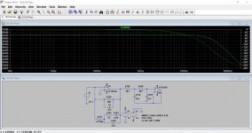
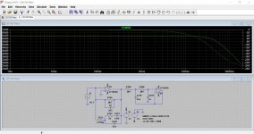
The circuit is almost identical to that used by Philips in early players.
This shows the standard Philips arrangement vs your values. You can see the 'gain' works out according to how stratus explained it. Good 'innit 🙂
Yours has a little more HF roll-off in the audio band.
This shows the standard Philips arrangement vs your values. You can see the 'gain' works out according to how stratus explained it. Good 'innit 🙂
Yours has a little more HF roll-off in the audio band.
Attachments
Do you use a digital interpolation filter with built-in correction for the analogue filter? If so, the analogue filter has to match the digital filter.
If not, what sample rates do you normally use? Do you want to compensate for the sin(x)/x roll-off of the hold function or do you like it rolled off a bit?
Are you the only one listening or is there someone with much superior high-frequency hearing accompanying you, like a cat or a dog?
If not, what sample rates do you normally use? Do you want to compensate for the sin(x)/x roll-off of the hold function or do you like it rolled off a bit?
Are you the only one listening or is there someone with much superior high-frequency hearing accompanying you, like a cat or a dog?
This is a brief cookbook article I wrote for this circuit if you are interested. There is a TINA-TI sim for it as well.
http://www.ti.com/lit/pdf/SBAA333?jktype=tech_docs
http://www.ti.com/lit/pdf/SBAA333?jktype=tech_docs
- Status
- Not open for further replies.
- Home
- Source & Line
- Digital Line Level
- Help to understand this NE 5532 op amp IV circuit