Guys,
I lately was gifted a pair of big opt, and they are 3"x4"x3.5" H.
There are 3 wires on one side and 4 on the other. I did some measurement, both are identical.
Yellow - Green 367.1 Ohm
Y.... - Red 187.2 Ohm
Green - Red 180 Ohm
Black - Grey 0.6 Ohm
B.... - White 0.5 Ohm
B.... - Green 0.8 Ohm
Please help to find out they are PP, and or SE w UL ??? How many K at primary.😕
Thanks
Albert
I tried to upload the photo. It said 'done', but nothing show on the first post. I'll try one more time later.
Put Mains voltage (110 or 230 ? pls tell us) on Yellow and Green and tell us the voltages you mesure on the secondary side.
Measuring just DC resistance won't help you to find the Z cause it depends on wire length and gauge and is thus under-determined. So we must know the ratios !
Measuring just DC resistance won't help you to find the Z cause it depends on wire length and gauge and is thus under-determined. So we must know the ratios !
It looks like a push-pull transformer with multiple secondaries
Do you have a signal generator and a true RMS meter or o'scope ?
Do you have a signal generator and a true RMS meter or o'scope ?
Albert,
What you have here are obviously PP output transformers (w/o) screen taps with a secondary of three output impedances. First, you must determine the turns ratio from the full primary to the three secondary output leads. From this you can determine the primary impedance using the formula Zp=N^xVp/Vs; that is assuming that you know the secondary impedances. The secondary impedances are likely 4, 8 & 16 ohms, but this is only a wild first guess; they could be different, but this is a starting place. The secondary common is likely the black wire. The white could be a 4 ohm tap, the grey an 8 ohm tap and the green the 16 ohm, but this is only a first guess. If the output voltage on the assumed 4 ohm tap is 1/2 the voltage of the assumed 16 ohm tap while the 8 ohm tap is .707 of the 16 ohm tap voltage then there is a fair chance that you have assumed correctly. I would not recommend applying the mains voltage to the primary as an inadvertent short could destroy the transformer or worse rather use a signal generator. If the calculated primary impedance is the same, say, 5,000 ohms or thereabouts from the three output taps then you likely have assumed the correct secondary impedances. Drive the secondary (assumed 8 ohms) with a largish SS amp while noting the waveform on a scope and determine the maximum power capability at, say, 20 Hz (which will be where the waveform starts to distort). If the maximum Po roughly corresponds with other known output transformers of equivalent size then you likely have guessed correctly. Then load the 8 ohm tap with an 8 ohm power resistor and drive 1/2 of the primary with a 1 - 5 kHz square wave (directly by a 600 ohm generator - to roughly simulate the rp of a DHT) and note the overshoot and ringing characteristics. Then, using a sine wave determine the -3dB HF roll off point. If it is ~20 kHz or higher then they could be used with triode power tubes. If substantially lower then they are suitable only for pentode operation.
What you have here are obviously PP output transformers (w/o) screen taps with a secondary of three output impedances. First, you must determine the turns ratio from the full primary to the three secondary output leads. From this you can determine the primary impedance using the formula Zp=N^xVp/Vs; that is assuming that you know the secondary impedances. The secondary impedances are likely 4, 8 & 16 ohms, but this is only a wild first guess; they could be different, but this is a starting place. The secondary common is likely the black wire. The white could be a 4 ohm tap, the grey an 8 ohm tap and the green the 16 ohm, but this is only a first guess. If the output voltage on the assumed 4 ohm tap is 1/2 the voltage of the assumed 16 ohm tap while the 8 ohm tap is .707 of the 16 ohm tap voltage then there is a fair chance that you have assumed correctly. I would not recommend applying the mains voltage to the primary as an inadvertent short could destroy the transformer or worse rather use a signal generator. If the calculated primary impedance is the same, say, 5,000 ohms or thereabouts from the three output taps then you likely have assumed the correct secondary impedances. Drive the secondary (assumed 8 ohms) with a largish SS amp while noting the waveform on a scope and determine the maximum power capability at, say, 20 Hz (which will be where the waveform starts to distort). If the maximum Po roughly corresponds with other known output transformers of equivalent size then you likely have guessed correctly. Then load the 8 ohm tap with an 8 ohm power resistor and drive 1/2 of the primary with a 1 - 5 kHz square wave (directly by a 600 ohm generator - to roughly simulate the rp of a DHT) and note the overshoot and ringing characteristics. Then, using a sine wave determine the -3dB HF roll off point. If it is ~20 kHz or higher then they could be used with triode power tubes. If substantially lower then they are suitable only for pentode operation.
Albert,
The formula in my previous post inadvertently omitted the 2 in the N^2 (N squared) part of the equation, plus I apparently jotted the formula down w/o thinking. In any event, N=Vp/Vs. Zp=N^2*Zs. Or Zp=(Vp/Vs)^2*Zs. It is most convenient to make up a little three row spreadsheet to do the primary impedance calculations for each of the secondary taps using their assumed impedances and voltage measurements. If you have guessed the secondary impedances correctly the taps will all indicate the same primary impedance, if not then you can easily juggle the secondary impedance values to make them all come out equal. This is much quicker and and easier to make everything jive than doing it long hand or with a calculator.
Dan
As a cheap and easy alternative to line voltage or a signal generator, if neither of these is practical, one could use an AC step-down transformer or wall-wart power supply of known voltage, correct? (Stressing, of course, that it's confirmed to be an AC supply, not DC.) Then derive the turns ration from that.
These are not uncommon in 12, 16, 24 VAC sizes. Maybe there's something in your junk box.
..Todd
These are not uncommon in 12, 16, 24 VAC sizes. Maybe there's something in your junk box.
..Todd
Albert,
The formula in my previous post inadvertently omitted the 2 in the N^2 (N squared) part of the equation, plus I apparently jotted the formula down w/o thinking. In any event, N=Vp/Vs. Zp=N^2*Zs. Or Zp=(Vp/Vs)^2*Zs. It is most convenient to make up a little three row spreadsheet to do the primary impedance calculations for each of the secondary taps using their assumed impedances and voltage measurements. If you have guessed the secondary impedances correctly the taps will all indicate the same primary impedance, if not then you can easily juggle the secondary impedance values to make them all come out equal. This is much quicker and and easier to make everything jive than doing it long hand or with a calculator.
Dan
Dan,
My friend has a signal generator and scope. Might be I can ask him to help with this.
Thanks you all for the input
Albert
Put Mains voltage (110 or 230 ? pls tell us) on Yellow and Green and tell us the voltages you mesure on the secondary side.
Measuring just DC resistance won't help you to find the Z cause it depends on wire length and gauge and is thus under-determined. So we must know the ratios !
I could use a 24v ac step down at the primary. Which lead I should connect to, Red/green, Red/yellow or yellow green.
BR
Albert
The _ manta,
I Put 28v AC on Yellow and Green and get the following numbers on secondary.
BLK - Green 1.26V
BLK - Grey 0.93v
BLK - Yellow 0.66v
Thanks
Albert
I Put 28v AC on Yellow and Green and get the following numbers on secondary.
BLK - Green 1.26V
BLK - Grey 0.93v
BLK - Yellow 0.66v
Thanks
Albert
According to the formulas above - and assuming the 0.93V reading represents the 8-ohm secondary tap - the plate-to-plate primary impedance = (28/0.93)^2 * 8 = ±7.25 kohms.
Sounds like a nice start for a couple of 6V6's or EL84's...
Sounds like a nice start for a couple of 6V6's or EL84's...
According to the formulas above - and assuming the 0.93V reading represents the 8-ohm secondary tap - the plate-to-plate primary impedance = (28/0.93)^2 * 8 = ±7.25 kohms.
Sounds like a nice start for a couple of 6V6's or EL84's...
Mr. Zenith,
Thanks a bunch.
I don't have the recommended tubes, but lots of 807. The size of the opts are kind of big. 3"x4"x3.5"H. What do you think ??
Albert
but lots of 807. The size of the opts are kind of big. 3"x4"x3.5"H. What do you think ??
Albert
807's will work:
http://frank.pocnet.net/sheets/084/8/807.pdf
Scroll down a few pages and look at the examples for AB1 PENTODE operation. With a 7.2K PP impedance, use 425-450 volts for the plate voltage and 300v for G2. That should be about right.
Can you post a picture of the transformers? See if your camera can take pictures at 640 X 480 resolution. Most likely the pictures you are taking are too big for this forum to accept.
Daniel
807's will work:
<snip>
http://frank.pocnet.net/sheets/084/8/807.pdf
Can you post a picture of the transformers? See if your camera can take pictures at 640 X 480 resolution. Most likely the pictures you are taking are too big for this forum to accept.
Daniel
Or use photo editor software to resize your pictures. Open source (free) GIMP works very well for this.
The recommended operating point makes sense to me, should end up with a pretty nice amp if the transformers are decent.
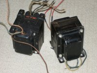
The fact that the laminations are assembled in blocks indicates they took some shortcuts in assembly.
On the other hand they did include end-bells and it looks like insulating washers to prevent magnetic shorts by the screws.
On the other hand they did include end-bells and it looks like insulating washers to prevent magnetic shorts by the screws.
The fact that the laminations are assembled in blocks indicates they took some shortcuts in assembly.
I am going to go out on a limb and say that Bogen made those transformers. What tipped me off is their build "style" and the red/orange date stamp. I have several Bogen power and output transformers that have this exact same date stamping on them. They are quality made transformers; mostly made for PA service, but some of them work quite well in a HiFi amp.
As for the laminations... I have some Sansui outputs where the laminations are put together in this "block" style and they are EXCELLENT output transformers. They have multi-interleaved coils and have very wide bandwidth.
Daniel
- Status
- Not open for further replies.
- Home
- Amplifiers
- Tubes / Valves
- Help to find out what OPT are these