I know there’s a lot of members of this forum who are also a member of the FB, Vintage Audio and Tech forum. I hope none of them will feel offended I’m posting here. As a total electronics noob, I need all the help I can get!
I’ve been restoring a B&K, AV5000 S2 that has one problem left to solve to complete the project. Channel 4 has a very faint speaker “hum/buzz” that’s there no matter what is or isn’t connected to the input. All 5 channels play and sound great, but when you turn channel 4’s volume down you can hear the hum/buzz. I’m pretty sure its not the power supply. Channel 4 shares its power supply connection with channel 5 that’s dead quiet. Also the noise is still there if you swap channel 4’s power connection with any of the other 4 channel’s connection. I’ve also checked solder joints, wire routing and ground connection problems and all seem to be OK.
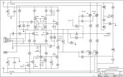
One suggested source could be V+, C2 and V-, C12; 100uF, 100V caps. The caps in it tested as: C2: 97.79uF, ESR=1.18 ohm, Vloss=1.2% and C12: 103uF, ESR=.38 ohm, Vloss=.8%. I also suspected the 10uF, 25V, bi-poplars, C7 which leads between the 4 mosfets and C8 because its the first component from the plus side of the input. They tested as C7: 12.3uf, ESR=1.5 ohm, Vloss=3.4% and C7: 12.6uF, ESR=1.6 ohm, Vloss=3.3%. I’ve read on a “Electronics For Dummies” site the Vloss values might indicate the caps are out of spec and should be replaced. Another suggestion is CT: 100uF, 25V, that’s on the schematic and board, but not listed in the BOM. It tests as 100.uF, ESR=.75 ohm, Vloss=2.0%.
While I’m capable of doing the testing and soldering replacement parts, I don’t have the diagnostic knowledge that would tell me what the test numbers mean and what else could be the cause of the hum. Its been a long summer sourcing and replacing parts (20 mosfets!) cleaning up issues left by previous work. I feel so close to success, but could really use some technical help and guidance finishing up this project.
Thanks
I’ve been restoring a B&K, AV5000 S2 that has one problem left to solve to complete the project. Channel 4 has a very faint speaker “hum/buzz” that’s there no matter what is or isn’t connected to the input. All 5 channels play and sound great, but when you turn channel 4’s volume down you can hear the hum/buzz. I’m pretty sure its not the power supply. Channel 4 shares its power supply connection with channel 5 that’s dead quiet. Also the noise is still there if you swap channel 4’s power connection with any of the other 4 channel’s connection. I’ve also checked solder joints, wire routing and ground connection problems and all seem to be OK.
One suggested source could be V+, C2 and V-, C12; 100uF, 100V caps. The caps in it tested as: C2: 97.79uF, ESR=1.18 ohm, Vloss=1.2% and C12: 103uF, ESR=.38 ohm, Vloss=.8%. I also suspected the 10uF, 25V, bi-poplars, C7 which leads between the 4 mosfets and C8 because its the first component from the plus side of the input. They tested as C7: 12.3uf, ESR=1.5 ohm, Vloss=3.4% and C7: 12.6uF, ESR=1.6 ohm, Vloss=3.3%. I’ve read on a “Electronics For Dummies” site the Vloss values might indicate the caps are out of spec and should be replaced. Another suggestion is CT: 100uF, 25V, that’s on the schematic and board, but not listed in the BOM. It tests as 100.uF, ESR=.75 ohm, Vloss=2.0%.
While I’m capable of doing the testing and soldering replacement parts, I don’t have the diagnostic knowledge that would tell me what the test numbers mean and what else could be the cause of the hum. Its been a long summer sourcing and replacing parts (20 mosfets!) cleaning up issues left by previous work. I feel so close to success, but could really use some technical help and guidance finishing up this project.
Thanks
Attachments
Last edited by a moderator:
One suggested source could be V+, C2 and V-, C12; 100uF, 100V caps.
If you have not tried that, and you don't have better idea, remove C2 and C12 all together, to see whether the hum is fixed or not.
Another thing from your schematic, I notice there are 2 ground pins from the connector. You may verify these 2 ground pins should have 0 DC resistance. Measure the resistance from the board, when the connector is connected, and the amp is powered off.
Edit: another way, you could measure DC voltage of these 2 ground pins from the board, when the amp is powered on. There should be 0 volt.
Edit: another way, you could measure DC voltage of these 2 ground pins from the board, when the amp is powered on. There should be 0 volt.
Last edited:
Thanks for the helpful reply!
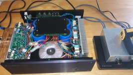
Lucky I was able to source replacements for the 100uF, 100V caps that are due to be delivered today. I've got the amp board out and off its heat sink so I could check solder joints and ready for the instillation of the replacement caps. The original caps were Rubycon, CE-Ws that are no longer made. All I could get are Panasonic, FCs I'm told are equal quality. Any thoughts?
I've also checked the continuity and resistance from the center pin (green wire) of the molex input connector to the chassis and the screw thread main ground. It seems to be fine from the connector thru the input board RCAs. With the board out it should be easy to check the continuity from the pins to the grounds.
Is the J1 link in or out, and whichever it is, is it the same as the other channels? Does C10 measure ok?
Is the J1 link in or out, and whichever it is, is it the same as the other channels? Does C10 measure ok?
That's what I was trying to say regarding the ground.
J1 is on all channels connecting CON 1, pin 3, green wire, ground from the input board of RCAs (so I'm guessing its "out" from the amp) to the negative lead of C10. C10 is a 100uF, 25V, that tested: 100.1uF, ESR=.69 ohm, Vloss=1.5%.
I've attached a pdf of the amp's service manual. Working off the same data should make communications tons easier!
Thanks again
Gene
I've attached a pdf of the amp's service manual. Working off the same data should make communications tons easier!
Thanks again
Gene
Attachments
I just checked the connections between channel 4, pin 3 solder joint and both ends of J1, good continuity with maybe .1 ohm or less. And all three of those points and the main ground and channel 4's negative post. All three points test for good continuity and less than .1 ohms. I'm using a fairly cheap meter that only goes down to 1 decimal place on it lowest 200 ohm range.
Morning, at least its morning here in SW Virginia!
Late Monday I received the replacement 100uF, 100V caps and the 10uF, 25V will be here today. So, I'll probably won't get to get them in till tomorrow morning and hopefully the amp back together and tested that afternoon.
BTW, johnmath I see your in Ausland. I'm a former F1 engineer for Mclaren and Arrows GP and have been to Adelaide and Melbourne. Always had a great time!
A former McLaren F1 engineer on DIYA! That’s is super cool. What season were you active and whose cars did you work on?
In my experience, hum is generally a ground loop on the input or perhaps lack of proper grounding on the amp in general. Chassis/earth ground (dirty) and analog 0v ground (clean ground) need to be separate and only connected deliberately and with star hub topology and the clean and dirty side need to be separated with a ground loop breaker (typically a 10ohm resistor parallled with back to back diodes or an NTC).
To debug, try connecting only one audio input at a time to the amp input. Use something battery powered like your phone or MP3 player connected through an RCA. Such a source is not connected to the mains anywhere so eliminates a source of hum. Also, remove any extra preamps, etc in signal path. Get it down to pure source to amp to speaker.
Using a DVM in AC rms mV mode connected to speaker out is a good way to see hum. A good quiet amp should be less that. 0.2mV rms. Hum is usually 1.0 to 1.5mV or rms or higher at the speaker out with no music playing.
If it plays music from that isolated single channels source without hum, the fault is a ground loop on the input, not the amp or it’s aging capacitors etc.
Last edited:
The Grand Prix made Adelaide! Before that there was no cafe society, pub's closed at 10pm and on Sundays, and no alcohol outside of a pub without a sit-down meal. I drove a parade lap for BMW's 75 Anniversary in '92 (BMW were the main sponsor in Adelaide for a number of years) and was given a 24 hour, 4 day, all areas pass that year, which unfortunately did not include the F1 pits. But I got to take home supermodel Elle McPherson's celebrity BMW 320i in race livery with the number plate ELLE and drove it around Adelaide for a week. Doctor Stephen Lewis who performed the on-site tracheotomy of Mika Hakkenin after his near death accident at Brewery Bend in '95 was an acquaintance of mine through the BMW Drivers Club. The drivers seemed to love Adelaide and they'd always head straight for Mount Thebarton indoor skiing slope on those 40ºC days - LOL. At the time I lived within ½km of the circuit in the city center, none of which helps solve the hum problem!BTW, johnmath I see your in Ausland. I'm a former F1 engineer for Mclaren and Arrows GP and have been to Adelaide and Melbourne. Always had a great time!
Last edited:
Morning, I was at Adelaide that year, 95! I can tell you the whole team was totally upset and scared for Mika. We knew it was a lot worse than it initially looked, because the data lads had the Gs from the hit. Also, when we got the car back there was a dent on the top of the steering wheel. That meant the 100mm wide shoulder harness straps actually stretched (the reason the seat belts in you car have pre-tensioners!) and his head hit the wheel. Mika always had the reputation of being aloof, but actually he was far from that. He is very shy, complicated by at the time his English wasn't great. So, he avoided or at least made as short as possible his contacts with the press. We originally met in 1990 when we were both doing British F3, him driving, me my first European track engineering. Fun times! But by 2000 I got enough and ended up at Ford, then graduate school and academia. I have to say I'm glad I got into the "business" when I did (started as a mechanic back in 1973!) and got out when I did. When I got into it, I got to meet and call friend a lot of the people I read about as a kid in the car rags. In those days racing was dangerous, but the life was more fun than a human-being should be allowed to have. We fought, drank, played tricks on each other and of course raced, each other hard and laughed about it afterwards. By 2000 most of them were gone or left racing and it was just paddock politics, business and money. It got so paranoid they didn't want you even chatting with someone from another team. It just stopped being fun and you start to wonder,"Why am I doing this?." That's when you know its time to get out and find something else to do. Lucky I had good contacts at Ford and fell into a fantastic job in Safety Systems. But as you said, that isn’t solving the hum in my amp! LOL
Morning again. After I finished up my earlier post it seemed like a good opportunity to use the early morning (5:30AM) quiet time to solder in the 4 replacement caps. Its now just after 7:30AM and the job's done, the amp is back on its heat sink and connected to the amp ready for testing. To avoid any neighbor issues (I'm in a townhouse) I'm waiting till after 10ish to give it a try. Wish me and the amp luck!
Attachments
Hi Gene
Remove Connector 1 for Channel 4 and shorten Pin 3 and 5
If it still hums, then shorten PIN 5 to CHASSIS GND. now if the AMP is working Ok it should be dead quiet..Then you have a GND Problem prior to input of main AMP.
Read Post Help Solving A Hum In One Channel and follow the advice.. I think the same way.
If this removes the Hum then it's before that connector where the HUM comes from.
Pin 5 is Signal input to Power Amp and Pin 3 is GND..
Don't worry nothing breaks..
Also I see there is a J1, which I think connects to Volume control of that Channel, is this VOLUME still OK? Measure continuity for that part. I just saw that you already did that.
If there is a mechanical problem with that VOLUME, then the results will be similar to that what you got... Either Pin1 or Pin 3 of the Volume has lost connections.. I think it's more pin 1, cause this connects to GND, and if this fails, because the track inside is bad then it hums.. check it out..
Usually Volumes controls are connected Pin 1 GND, Pin2 Output and Pin 3 input.. if you check out the circuit then you can see that there is a J1 which breaks the GND PATH from Pin 3 Connector 1, make sure that you got continuity there.
Last edited:
Hpro, thanks for the advice! Before I reassembled the amp I went through the input board with a DVM checking continuity and resistance. Everything seemed to be connected as it should to the board ground and the screw post main ground. All 5 pots smoothly changed resistance as they're rotated. Just to be sure, I re-flowed all the pot and connector pin joints. Also before I reattached it to its heat sink, I checked continuity from pin 3, green ground wire through J1 jumper and from J1 to the cap it connects. All seemed to be fine. From my automotive electronics experience I know the solder joints of connector pins always seem to go bad. So, I clamped a hemostat across the 5 pins to hold them in place, sucked the solder off each pin and re-soldered the joint. After all that I reconnected the amps board back to the amp and fired it up. It works and channel 4 seems to be as quiet as the other 4. I won't get to work on it again till tomorrow. Am I correct in thinking after replacing the caps, I'll need to set the bias and DC offset? Thanks again!
Attachments

I think if you resoldered the spots you wrote, then it was merely a bad contact which caused the problem .
Measure DC output if there is not more than 1millivolt just leave it.. It will neither hum nor making any other noise..
Use a ANALOQUE DC voltmeter where you can measure Millivolts, and set a Signal say 1Khz to the input of the AMP and then move the Attenuator fast forward and backward, and check how much DC at the output changes..Or just give a 10HZ signal on low level at the input and check out DC... shouldn't Jump..
Trust you self because you got ot run again.
Enjoy weekend.. hope it sounds good.
Chris
I've been setting the bias and DC offset with no signal input. I'll have to see if I can borrow a signal generator, or I've seen PC/USB based generator software for Linux. One question I'm still unclear is what value to set the bias. There seems to be lots of speculation and formulas. like: 100mA per mosfet pair plus 50mA for the rest of the electronics, 250mA. I found a several years old post here on diyAudio from someone who's doing the same job I am. He called Elite Audio (that's the audio company started by George and other B&K refugees) and was told set all channels to 150mA. B&K AV5000 help needed. Any thoughts?
Of course I have some thoughts.
1. Signal gen you can download for any Android Mobil Phone, I think even Apple does have an app.! then use the headphone jack, these Signal Gens are quite good. distortion is less than 0.2% and thats more than enough... 20 / 20k is also more than it needs..
2. did you change anything on one of the other AMPLIFIERS blocks in there?
if not measure one or two of them and then adjust bias similar to these,,
Piece of cake...
3. take the repair manual and read it, check the mosfet Number and look at the datasheet..
4.Last but not that easy calculate it.. And I think you are able to calculate that, too many apps on the internet.. use PAPA GOOGLE.
Have fun..
Regards
Chris
Bias and offset are normally set without input or output connected. The B&K runs about 125 watts at idle, which means the amp will run hot, but 250mA per channel is quite high. If Elite says set it to 150mA, that is what I would do and that setting is more consistent with the idle power consumption. The exact bias setting isn't particularly critical for sound quality (except for amps where the setting is very close to the crossover point of the output devices, which is not this one!) Setting it too high just stresses everything unnecessarily. Think of bias as like setting the idle rpms on an engine: you want to run smooth at idle, not blow up the motor running it too fast with no load. Make sure the amplifier is well ventilated and don't stack it close to other components.
Regarding the hum, if the circuit board in grounded by a screw to chassis andhas a ground connection through the loom, then the potential exists for a ground loop. Are all the boards connected like this? Does it hum with that screw removed?
B&K are quite responsive to enquiries, so you could email or call them. Have the serial number handy.
Are you going to use all channels or just 2 or 3? If you have spare channels you can do a couple of things. You could remove the fuses for the unused channels to reduce electricity consumption and heat dissipation. Alternatively if your speakers allow it you can bi-amp and bi-wire the main stereo pair, which may give you a worthwhile benefit in sound quality.
Last edited:
Morning, Johnmath, Hpro. Johnmath do you know B&K went out of business back in 2010? Unfortunately, Eastern Elite Audio Video, George Reamsynder’s company is also gone. While as a customer I got great service, I’ve been told B&K didn’t treat the independent repair businesses very well. If they called B&K for help repairing a unit, B&K refused any professional courtesy and just told them to send it to Buffalo. Besides age, this is the reason B&Ks are now repair orphans. Almost all independent repair shops say they won’t touch anything B&K.
In automotive terms I perceive bias is like the idle mixture and DC offset as the idle speed adjustments. Attached is a B&K document with the bias and DC offset procedures. Am I correct in reading after checking the rail amperage, disconnect the signal generator and remove the 8 ohm resistors before setting the bias and DC offset? My current safety unit is a dim bulb tester with a 150W bulb! After replacing the mosfets I found all 5 biases were between 69.7mA and 112.7mA and the offsets at -.01mV to .23mV. I adjusted all to 150mA and 0.00 to .01mVs. I replaced the “Brand X” mosfets (originally all the 2SK1058s were replaced with units that had K16H written on them and the 2SJ162s had “J162” on them, but tested way out of spec., probably fakes! ) with Excon: ECX10P20s and ECX10N20s that are supposed to be direct replacements for the Hitachi/Renesas components. But I wonder if they might need a slightly different bias setting. Yesterday I sent an email to Excon tech asking the question. The answer should be interesting!
Hpro, since I’ve replaced all 20 mosfets, adjusting the bias and DC offset was a necessity. Over the months I’ve been involved with this project I’ve become very familiar with the service manual, but nowhere in it does it mention or provide instructions or values for setting the bias or DC offset. And “yes” I probably could eventually get through the math. Like the majority of engineers, I’ve moved on to other work (I run a technology policy shop) and my maths, calculus skills are a bit rusty! So, any help and/or direction on setting the bias will be greatly appreciated.
Attachments
- Home
- Amplifiers
- Solid State
- Help Solving A Hum In One Channel