Hello everyone.
I never designed neither built a push-pull tube amplifier.
I know how to do it using the datasheet curves, and I have the theory for numerical calculations, so it's time to move to practice.
I'm currently working on simulating a simple AB output stage (on LTspice), but I'm getting trouble to get a decent output.
- If I use an small signal input, the output is nice, but both tubes are working all the time (so we have a class A push-pull, not what I want).
- If I increase the input level, then each tube cuts-off during a portion of the cicle, which is what I want (class AB), but the output is not a sine anymore.

I used Va = 300 V, Rk = 270 ohm and 36 mA per tube quiescent current, as Mullard's datasheet recommends.
In the attached image and circuit I'm not using decoupling cathode capacitors, but when using them, I get the same problems (jut gain is much higher) of either nice class A output, or flattened top/bottoms class AB output.
I tried many variations, like cathode resistors, from 100 to more than 1k.
Any help? Thank you very much.
By the way, I'm using Duncan Munro's EL84 model (attached too).
If I try Ayumi Nakabayashi's model, I get an error of too smal timestep, which I don't know how to solve yet.
I never designed neither built a push-pull tube amplifier.
I know how to do it using the datasheet curves, and I have the theory for numerical calculations, so it's time to move to practice.
I'm currently working on simulating a simple AB output stage (on LTspice), but I'm getting trouble to get a decent output.
- If I use an small signal input, the output is nice, but both tubes are working all the time (so we have a class A push-pull, not what I want).
- If I increase the input level, then each tube cuts-off during a portion of the cicle, which is what I want (class AB), but the output is not a sine anymore.
I used Va = 300 V, Rk = 270 ohm and 36 mA per tube quiescent current, as Mullard's datasheet recommends.
In the attached image and circuit I'm not using decoupling cathode capacitors, but when using them, I get the same problems (jut gain is much higher) of either nice class A output, or flattened top/bottoms class AB output.
I tried many variations, like cathode resistors, from 100 to more than 1k.
Any help? Thank you very much.
By the way, I'm using Duncan Munro's EL84 model (attached too).
If I try Ayumi Nakabayashi's model, I get an error of too smal timestep, which I don't know how to solve yet.
Attachments
I modified your circuit and now some 14 W out. Is this OK ?
I think you attached the same circuit I posted. Could it be?
Output transformer was 16k to 8 ohms, now 8k to 8 ohms and cathode resistors were not connected.
Thanks for the information. I thought an 8k transformer meant that BOTH plate inductor should be 1000 bigger than speaker side (when using an 8 ohm load, obviously). Thus the values 50+50 and 0.1 for the inductors.
and cathode resistors were not connected.
Do you mean cathode capacitor? I just checked my circuit, and cathode resistors are connected.
jazbo8, I know, but the output is far from what I would consider ok for an audio amplifier. Don't you think? The output wave is obviosly disfigured.
Not really commenting on the simulation, but just don't expect to duplicate what the datasheet says in this case. And as mentioned by artosalo, the OPT ratio and the input voltage has to be adjusted. Then try the simulation again.
I think you attached the same circuit I posted. Could it be?
That really happened, sorry. Let's try again.
In case of pp-output transformer, the load impedance is determined as anode to anode.
In the circuit I modified there is now 40H total primary inductance, so one primary is 10H.
Do you mean cathode capacitor?
Yes.
Attachments
In the circuit I modified there is now 40H total primary inductance, so one primary is 10H.
Thanks for your help, now with a few changes I got the output stage I was looking for.
Just, I don't understand the output transformer inductances. Why 10H each primary winding if total inductance must be 40H?
A reminder of the turns ratio:
An externally hosted image should be here but it was not working when we last tested it.
Just, I don't understand the output transformer inductances. Why 10H each primary winding if total inductance must be 40H?
Below is the "general" equation of the inductor. As you see the inductance depends on the number of turns as "n²".
When the number of turns is doubled the inductance is quadrupled.
I know, but I might be getting something wrong.
Impedance ratio is:
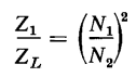
Inductance is proportional to the turns ratio squared.
Shouldn't then, inductance ratio be equal to impedance ratio?
Lp/Ls = Zp/Zs = (Np/Ns)^2
In LTspice we are concerned about inductances, not turn ratios (aren't we?).
So, if we want 8 kohm for an 8 ohm load, we need a 1000 times impedance ratio. For example 40H for primary (20H + 20H, as it is center tapped), and 0.04H for secondary, and not 20H/0.04H.
Could you point me out where am I missing something?
Impedance ratio is:
Inductance is proportional to the turns ratio squared.
Shouldn't then, inductance ratio be equal to impedance ratio?
Lp/Ls = Zp/Zs = (Np/Ns)^2
In LTspice we are concerned about inductances, not turn ratios (aren't we?).
So, if we want 8 kohm for an 8 ohm load, we need a 1000 times impedance ratio. For example 40H for primary (20H + 20H, as it is center tapped), and 0.04H for secondary, and not 20H/0.04H.
Could you point me out where am I missing something?
When the inductors/windings are on a single core, the series connection of two inductors/windings doubles the number of turns, which has a square effect on the inductance, i.e., the inductance is quadrupled.
I've simulated three variations of a similar output stage, using three different screen bias methods:
- Simple resistor to drop 50 V quiscent (plus decoupling capacitor).
- Direct voltage supply (also, 50 V under plate voltage).
- Ultralinear, 40% tapping.
It seems that the simple resistor method delivers less distortion (1,11% @ 12,8W), followed by UL (2% @ 9,1W) and finally the direct supply (5% @ 16,4W).
Two things seem strange about UL. It is the most sofisticated and costly solution, but has high distortion, maybe even compared with the direct supply (because its almost 7W under).
Also, the push-pull seems to not be working, as both tubes are conducting all the time. They dissipate much more average power, and they peak at higher than the maximum 12W limit.

Looking at the simulation, I woul definitely not choose the UL desing.
Do you guys think this is just a simulation, not a real life result?
- Simple resistor to drop 50 V quiscent (plus decoupling capacitor).
- Direct voltage supply (also, 50 V under plate voltage).
- Ultralinear, 40% tapping.
It seems that the simple resistor method delivers less distortion (1,11% @ 12,8W), followed by UL (2% @ 9,1W) and finally the direct supply (5% @ 16,4W).
Two things seem strange about UL. It is the most sofisticated and costly solution, but has high distortion, maybe even compared with the direct supply (because its almost 7W under).
Also, the push-pull seems to not be working, as both tubes are conducting all the time. They dissipate much more average power, and they peak at higher than the maximum 12W limit.
Looking at the simulation, I woul definitely not choose the UL desing.
Do you guys think this is just a simulation, not a real life result?
Attachments
The UL tap ratio you used was incorrect, you want a voltage ratio of 43% or an impedance ratio of 18.49%.
But, isn't UL suppose to be a better approach (in terms of distortion)? and even UL sacrifices a bit of output power, the efficiency in the simulation has dropped a lot, and neither valve is off during any portion of the cycle. It defeats the class AB. Works like push-pull class A stage.
Why exactly do you say that?
From "theory and operation of the ultra-linear circuit":
The advantage of UL is that distortion is much lower [...] the linear characteristic is practically straight up to the grid current point, giving constant amplifier gain even without feedback.
Shows a drop in maximum power output [when constant supply voltage]
The efficiency may be made to be ALMOST the same as for pentode operation.
The screen dissiaption is less in UL operation [...] the disadvantages are slight loss in voltage gain, reduced power output [...]
If you mean about what I said about class A, that was based on my simulation, which is what I'm not sure if it's working the right way.
UPDATE: you just updated your post. Thanks for the tip, I'll investigate it.
Last edited:
Yes, all I meant to say was to double check the simulation before you question how UL works. Wrong inputs could lead to wrong results and conclusions...
jazbo8, now I understand what you meant 🙂 Thanks.
I reworked the inductances (screens around 40% plate voltage), and got better results, but not as I expected:
*THD is reduced from 2% to 1,48%. Nice!
*Output power is bumped up to 12W, which is very nice too (almost the same as with the non-UL using a simple screen resistor).
*But output tubes still don't reach cutoff (they nearly do, but not fully, as with the other non-UL AB setups). This means 8,9W average dissipation each, with peaks around 14W (above the 12W limit, which I suppose is not acceptable).

Won't this still be considered class A?
Also, the simple screen resistor setup achives even less THD, 1,11%.
Isn't it strange?
I reworked the inductances (screens around 40% plate voltage), and got better results, but not as I expected:
*THD is reduced from 2% to 1,48%. Nice!
*Output power is bumped up to 12W, which is very nice too (almost the same as with the non-UL using a simple screen resistor).
*But output tubes still don't reach cutoff (they nearly do, but not fully, as with the other non-UL AB setups). This means 8,9W average dissipation each, with peaks around 14W (above the 12W limit, which I suppose is not acceptable).
Won't this still be considered class A?
Also, the simple screen resistor setup achives even less THD, 1,11%.
Isn't it strange?
Attachments
Hi
@Elerion
Be carefull with distorsion results from simulation : it is the distorsion of the mathematical model used for the tube !!!!
In addition, your OPT doesn't take into account losses, parasistic capacitances, leakage inductances, ....
Jacques
@Elerion
Be carefull with distorsion results from simulation : it is the distorsion of the mathematical model used for the tube !!!!
In addition, your OPT doesn't take into account losses, parasistic capacitances, leakage inductances, ....
Jacques
- Status
- Not open for further replies.
- Home
- Amplifiers
- Tubes / Valves
- Help simulating push-pull AB output stage