Hi ya,
I just moved home and lost my creative inspire 4.1 4400 sound control unit. I looked online to find it and didn't find any, also did some search and came to know that Creative doesn't provide these spares. Please help me build it or an alternative, till then my PC sound is as good as dead.
Thanks,
Siddu
I guess it is difficult to tell what circuitry was inside that sound controller unit unless one owns and dissects it.
If there is only a potentiometer then it's the best to open the cabinet carefully taking precaution and understand the sections and post some pictures here so that the experts can guide you.
A control unit for sure can be made imho once you know which chips are used in that.
All the best.
If there is only a potentiometer then it's the best to open the cabinet carefully taking precaution and understand the sections and post some pictures here so that the experts can guide you.
A control unit for sure can be made imho once you know which chips are used in that.
All the best.
Hi Csom,
Thanks for getting back to me and luckily I have a friend who has got the same sound system and I borrowed his control unit to take some pics. Please help me build one like this.
Thanks for getting back to me and luckily I have a friend who has got the same sound system and I borrowed his control unit to take some pics. Please help me build one like this.
Attachments
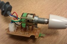

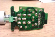
It appears to be a dual potentiometer with single-pole switch, and an LED and resistor (probably to limit current through the LED). You need to trace out the circuit, buy the bits and build a copy.
It appears to be a dual potentiometer with single-pole switch, and an LED and resistor (probably to limit current through the LED). You need to trace out the circuit, buy the bits and build a copy.
Is there a way to just connect some wires together and get the device to turn on and running? Am happy to control the volume from the PC.
Hi Csom,
Thanks for getting back to me and luckily I have a friend who has got the same sound system and I borrowed his control unit to take some pics. Please help me build one like this.
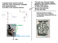
Here is an idea on how to do that. Also it would be convenient if we could know what chip was used in the power amp section.
IMPORTANT: This might be a DC volume control. So please read the attachment minutely.
All the very best 🙂
Attachments
It appears to be a dual potentiometer with single-pole switch, and an LED and resistor (probably to limit current through the LED). You need to trace out the circuit, buy the bits and build a copy.
I second that 🙂
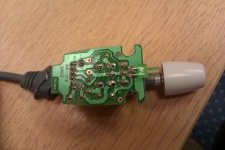
Probably, yes. Ignore the wires which go to the resistor, LED and switch - all they do is light the LED. Connect the input (top of pot) to output (pot slider). Connect the input ground to output ground.Is there a way to just connect some wires together and get the device to turn on and running?
Hello, this may have been solved long ago, but just in case I have found someone that has done something similar to what you are attempting here
Diya's life and journey through India...: A Quick Fix For Creative Inspire 4.1 4400 Speaker Volume Control Unit
Maybe you can help me. I do have the volume control unit, but it is cut on the miniDIN connector side.
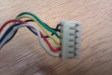
So I have the original potentiometer on one side, and a bunch of cables on the other side: yelow, red, green, black, white.
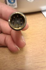
I assume I can buy a 6 pin male miniDIN connector and solder the cables to it, but... in which order? what colors where?
Thank you for your help.
Diya's life and journey through India...: A Quick Fix For Creative Inspire 4.1 4400 Speaker Volume Control Unit
Maybe you can help me. I do have the volume control unit, but it is cut on the miniDIN connector side.
So I have the original potentiometer on one side, and a bunch of cables on the other side: yelow, red, green, black, white.
An externally hosted image should be here but it was not working when we last tested it.
I assume I can buy a 6 pin male miniDIN connector and solder the cables to it, but... in which order? what colors where?
Thank you for your help.
Hi Plagasul,
When you have the original Potentiometer, why would you want to buy a 6pin maleDIN and do the soldering? Connect/solder the cut cables on the Potentiometer with the same matching color wires on the other side.
When you have the original Potentiometer, why would you want to buy a 6pin maleDIN and do the soldering? Connect/solder the cut cables on the Potentiometer with the same matching color wires on the other side.
Hello, thank you for your reply.
Maybe I do not understand well or have not explained myself well.
My volume control is working fine, the broken part is in the other side of the cable: the miniDIN connector that goes to the subwoofer.
So on one side of the cable I have a working volume controller, and on the other side, I have 5 cables.
I want to solder those cables to a miniDIN connector, to be able to plug it into the subwoofer, and so I can control the volume.
And my problem is that I do not know how to deduce the color code, as in what cable to solder to what pin in the miniDIN. If this can be deduced from the PCB, could you please explain to me how? that would be greatly appreciated.
I have started a specific post for my problem, with images and links and maybe there the problem is explained better.
Thank you VERY much for your help.
This is the other post
http://www.diyaudio.com/forums/part...l-unit-fix-connector-creative-4-1-4400-a.html
Thanks again
http://www.diyaudio.com/forums/part...l-unit-fix-connector-creative-4-1-4400-a.html
Thanks again
- Status
- Not open for further replies.
- Home
- Design & Build
- Parts
- Help replacing/building a control unit