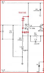
Not +15 but -15V I hope.
If pin2 is pulled up again to 64V by some other defect, Z1 is gone ones more.
The minus-in is pulled up and the output of Z1=base Q1 goes down.Clearly that is not the case, Q1-B=13.6V !
The emitter of Q1 is pulled up to 3.8V by the zener action of the b-e diode.
Mona
If pin2 is pulled up again to 64V by some other defect, Z1 is gone ones more.
The minus-in is pulled up and the output of Z1=base Q1 goes down.Clearly that is not the case, Q1-B=13.6V !
The emitter of Q1 is pulled up to 3.8V by the zener action of the b-e diode.
Mona
Last edited:
Actually, that's one of the reasons they used the LF35x. R4 limits the current enough that the op amp won't die if the amp is stuck to the rail. Not all op amps can take this without instant death or at least misbehavior.
I've tried "better" op amps in these amps (and other similar ones) and the first time they are driven to clipping or get stuck to a rail it's bye bye op amp. The LF351's (or 411/2's I usually use) take a licking and keep on ticking. I have seem my share of dead op amps, but usually the result of other failures - like open solder joints on the zeners which send the op amps supply through the roof. Usually getting stuck to a rail won't kill anything else.
I've tried "better" op amps in these amps (and other similar ones) and the first time they are driven to clipping or get stuck to a rail it's bye bye op amp. The LF351's (or 411/2's I usually use) take a licking and keep on ticking. I have seem my share of dead op amps, but usually the result of other failures - like open solder joints on the zeners which send the op amps supply through the roof. Usually getting stuck to a rail won't kill anything else.
Yes, as I said,put in the diodes.That way the IC is safe.Hi,
When pin 3 has +41.8 volt coming out means Z1 it is zapped. I recommended to lift one side of R12 to prevent keep zapping Z1 until we determined where the +52 volts is coming. Unless somebody have another better idea.
Mona
Great, I *JUST* replaced Z1.
I really don't have any idea how to pull anything to negative or where to install diodes. I can replace parts, and I can use a multimeter. That's about it. I can follow detailed instructions, but they can't make assumptions that I know what I'm doing")
Charles.
I really don't have any idea how to pull anything to negative or where to install diodes. I can replace parts, and I can use a multimeter. That's about it. I can follow detailed instructions, but they can't make assumptions that I know what I'm doing
Charles.
I have removed Z1 completely. The output is still at positive rail voltage. The readings at the pins of Z1 are:
pin 1: 0
pin 2: +62
pin 3: +61
pin 4: -15.6
pin 5: 0
pin 6: 0
pin 7: +15.8
pin 8: 0
With 60+ volts on both pin 2 and pin 3, I'm thinking bridging pins 4 and 6 with a resistor is probably a bad idea, as the problem is likely elsewhere.
Charles.
pin 1: 0
pin 2: +62
pin 3: +61
pin 4: -15.6
pin 5: 0
pin 6: 0
pin 7: +15.8
pin 8: 0
With 60+ volts on both pin 2 and pin 3, I'm thinking bridging pins 4 and 6 with a resistor is probably a bad idea, as the problem is likely elsewhere.
Charles.
With 60+ volts on both pin 2 and pin 3, I'm thinking bridging pins 4 and 6 with a resistor is probably a bad idea, as the problem is likely elsewhere.
Charles.
No it's not a bad idea. You will want to see if pins 2 and 3 follow one another, and that you CAN alter the phase of the output.
Your signal ground may be floating. Otherwise, current through your input bias resistor would drag the node down and you wouldn't get the full VCC at one of the opamp inputs. One thing I'd check now it whether there is a solid zero ohm connection between the RCA input shield and the junction between the two zener diodes. And between there and the connection between the two big power supply caps.
Well, that changed something for sure. I *think* it may be fixed.
My input was indeed floating. Now that it's attached and the op amp is back in the socket (I socketed the op-amp) the dim bulb tester is acting funny. Not sure if this means I'm good to go, or what.
Before, the bulb would get bright and then immediately dim. Now that I've fixed my floating input, it gets bright and then stays slightly dimmer. I can adjust the bias pot and get output voltage down to about +1.4v before reaching the end of the adjustment range. Adjusting the bias pot will dim or brighten the bulb. If I go too far the relay will disengage because of too much voltage on the output.
So my question now is... does this mean it's working? Why does the bulb not dim anymore? Even though the bulb is lit, I appear to be getting close to the optimal 0v DC offset on the outputs. Rail voltage is down to +/1 40v, which I'm guessing is because of the bulb. I'm wondering if removing the bulb will give me some range back to that bias pot, or if I'm going to have to replace it with a larger range. I'm also wondering if removing the dim bulb tester is going to fry anything, and wanted to ask here before I make that step. Kinda worried because the bulb is still lit.
Charles.
The bulb is lit (slightly on) because there is now quiescent current in the output and driver stages like there should be. You should be able to shut it most of the way off by underbiasing the amp. Check your bias adjust range, drive the amp to full output with no load. Look for oscillations (sudden jumps in the bulb brightness). If nothing stupid happens, underbias it and plug in direct. Check it again with no load. If it passes, set the bias properly, monitor it until warm and readjust if necessary.
- Status
- This old topic is closed. If you want to reopen this topic, contact a moderator using the "Report Post" button.
- Home
- Amplifiers
- Solid State
- Help repairing Phase Linear Series II Model 200