I'm an experienced installer but know very little about amplifier repair, so I was hoping you guys could help me! 
This amp was poorly mounted in a vehicle and probably slid around a lot. One day it quit working. It kept blowing the fuse on the power wire.
I took the amp out, took off the cover and blew the dust/debris out with compressed air. I connected the power (unfused) and ground and everything seemed okay, but shortly after connecting the remote, all three fuses on the amp popped. Only the power LED turned on between the time the remote was connected and when the fuses blew, never the thermal or protect LEDs. I can't find any visible damage on the board or components.
Any suggestions as to where to start testing things?
Id start checking the power supply fets and the outputs first off.
your multi meter set to ohms you should not read anything near 0 ohms between any of the legs on the power supply fets or the outputs,
The power supply fets and outputs are on the mesha boards ( 3 legged)
Cool, I'll start there and post results tonight.
My camera doesn't take the greatest quality pics, but I'll try to get the best pic I can.
Thank you very much
That's probably it. I looked there but overlooked it.
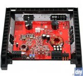
If the fuses only blow after remote voltage is applied, the output transistors (circled in photo) have likely failed.
If you apply power again before checking the output transistors, install only a single 10 amp fuse in one of the fuse holders. Leave the other 2 empty.
If the fuses only blow after remote voltage is applied, the output transistors (circled in photo) have likely failed.
If you apply power again before checking the output transistors, install only a single 10 amp fuse in one of the fuse holders. Leave the other 2 empty.
Attachments
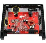
The two fets shown on the lower left of the picture show very low resistance, with the middle and right legs showing a dead short between them. The two fets on the top right of the picture (labeled CR5 and CR6 on the board) are reading a short between their left and right legs, but high resistance through the middle leg. These are power supply transistors, right?
So I take it all 4 of these should be replaced. Are there other components that could have failed after these did? Or could another component have failed first, and caused the fets to fail?
So I take it all 4 of these should be replaced. Are there other components that could have failed after these did? Or could another component have failed first, and caused the fets to fail?
CR5 and CR6 are the rectifiers. It's normal to read 0 ohms across the outer legs. You're reading across the transformer's windings.
Read post #29 before you attempt to replace the transistors.
http://www.diyaudio.com/forums/car-...-schematics-3.html?postid=1901581#post1901581
It's possible that other components have failed. After replacing the outputs, power it up with the single 10 amp fuse and have all transistors clamped tightly to the heatsink. If the fuse blows, we'll have to do further troubleshooting.
You should order several PZTA56s, PZTA06s and MMBT5087s (not sure which ones are used in this amp). These are used in larger amps as drivers and, in those amps, fail when the outputs fail.
CR5 and CR6 are the rectifiers. It's normal to read 0 ohms across the outer legs. You're reading across the transformer's windings.
Read post #29 before you attempt to replace the transistors.
http://www.diyaudio.com/forums/car-...-schematics-3.html?postid=1901581#post1901581
It's possible that other components have failed. After replacing the outputs, power it up with the single 10 amp fuse and have all transistors clamped tightly to the heatsink. If the fuse blows, we'll have to do further troubleshooting.
You should order several PZTA56s, PZTA06s and MMBT5087s (not sure which ones are used in this amp). These are used in larger amps as drivers and, in those amps, fail when the outputs fail.
So I finally got around to replacing the bad outputs and powered it up. The fuse did not blow, but the protect LED came on within a few seconds.
Next thing to check would be the drivers, right? How are they tested, and which ones need to be tested?
I did order some PZTA56s and PZTA06s (the MMBT5087s didn't look like anything used in my amp). I noticed that the ones in my amp say DF50 or DG25, whereas the ones I ordered say DH30 and DH42. Are they compatible or will I need completely different parts (given that they do need replacing)?
As long as the parts you ordered have A56 and A06 on their face and the case style is the same, they will fit.
Does the amp produce any DC across the speaker terminals when you power it up?
You'll need to have the meter connected before applying power and you'll need to watch it carefully as you apply power.
Does the amp produce any DC across the speaker terminals when you power it up?
You'll need to have the meter connected before applying power and you'll need to watch it carefully as you apply power.
OK, looks like I've got the right drivers.
Before powering it up, the amp has a small voltage that slowly approaches 0 measured at the speaker terminals (a draining capacitor?). When powered up, the DC voltage immediately goes to 0. At one point, while the power was hooked up a couple seconds longer, something made a POP sound so I removed remote power. But it still turns on just like before.
Oh, and should I be doing this with my 55 watt resistor in series with my B+ wire? I haven't done that yet.
- Status
- This old topic is closed. If you want to reopen this topic, contact a moderator using the "Report Post" button.
- Home
- General Interest
- Car Audio
- help repairing a RF T5001bd