Consider recapping that channel too. As,old as it is and as hot as they run I would certainly advise doing that while the board is out.
Yes, thanks, I've done a complete recap, apart from the massive beer can reservoirs. Sounds amazing now! I got quite a few hours out of it before the zener/regulator failed again.
This issue with the regulator seems to be a known problem to this amp.
http://www.audiotecnico.it/riparazi...s/immagini/Krell_KSA50s_regolatore_driver.JPG
Call Krell service department, I`m sure they will give you guidance...
http://www.audiotecnico.it/riparazi...s/immagini/Krell_KSA50s_regolatore_driver.JPG
Call Krell service department, I`m sure they will give you guidance...

I've have 4 KSA-50S to repair, forget what were the problem, but need to be repaired this time, hope some one can help.

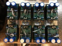
Label them to 4
Amp1
Burnt: 484024 x2, 0.5ohm E resistor had some mark
Pre-drive E resistor was 1ohm + 5.6ohm (others was 1ohm + 3.3ohm)
Amp2
Burnt: 10ohm, but don't know that was for +-45V' power or pre-drive transistor B.
Both channel had the D3, D12 burnt mark on board, but measured Diodes are good.
Amp3
Burnt: 484002 x1
Amp4
Burnt: 484002 x1 and related 0.5ohm, 3.3ohm, one 0.5ohm was broken.
-----------------
All pre-drive transistors are measured in good condition.
investigated so far
-----------------
Will do:
Re-caps all
Replace for:
all +-45V' 10 ohm power resistors from 2W to 7W
all +-18v zener 1N4740 & 1N4743 to 1N5349 (11.4V 5w), (get idea from earlier post of your guys)
all pre-drive B resistor 10ohm
all pre-drive E resistors 1ohm + 3.3 ohm
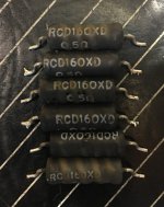
all power drive E resistor 0.5ohm to Dale or CadDock, because the time tells, RCD isn't that good.
-----------
Hope some one can give me any advise, please
-----------
Those amps are mine, they work for my active crossover, and separate speakers and speaker drivers for stereo channel etc...
Amp1
Burnt: 484024 x2, 0.5ohm E resistor had some mark
Pre-drive E resistor was 1ohm + 5.6ohm (others was 1ohm + 3.3ohm)
Amp2
Burnt: 10ohm, but don't know that was for +-45V' power or pre-drive transistor B.
Both channel had the D3, D12 burnt mark on board, but measured Diodes are good.
Amp3
Burnt: 484002 x1
Amp4
Burnt: 484002 x1 and related 0.5ohm, 3.3ohm, one 0.5ohm was broken.
-----------------
All pre-drive transistors are measured in good condition.
investigated so far
-----------------
Will do:
Re-caps all
Replace for:
all +-45V' 10 ohm power resistors from 2W to 7W
all +-18v zener 1N4740 & 1N4743 to 1N5349 (11.4V 5w), (get idea from earlier post of your guys)
all pre-drive B resistor 10ohm
all pre-drive E resistors 1ohm + 3.3 ohm
all power drive E resistor 0.5ohm to Dale or CadDock, because the time tells, RCD isn't that good.
-----------
Hope some one can give me any advise, please
-----------
Those amps are mine, they work for my active crossover, and separate speakers and speaker drivers for stereo channel etc...
It looks like no one interesting for my request.
Never mind, this amp is too old for everyone I believe.
All four amps have modified, re-caped and restored now, all work good.
The way to fix below:
They've had this common issue as all KSA-50S:
1. Two Zenners was not enough to drop the voltage down to lower than 35v, and they were running too hot then get break thru.
2. Then, the titan cap will be blowed, two of the amps had this issue.
3. Then, the regulator will be blowed, one of the amps has changed regulator before me.
Solution:
1. Change Zener to three 1N5340BG (10v, 5w), drop the voltage to 30v.
2. Change C6, C8 to 33UF/63v, that never blow up again even Zener over heat and get break thru.
3. Change regulators to NJM7818FA & NJM7918FA, they are 1.5A, higher than normal one 1A, and they have over voltage protection, tested, connect to 60v, output is 0v.
4. Change C7, C9 to 100UF/25v, stop the surge as much as it can. (may not need, but I like to do this)
5. The T-Cap in drive board, those don't need to change, unless died, my case one of the amps was.
6. Soldering:
All Zeners and regulators, soldered to the opposite side of PCB as before,
Zenners raise up 1.5mm from PCB.
Added a 3mm thick silicon conduct pad, between the Zeners, regulators and heat sink, let the heat sink spread the heat.
And that is all, hope they never get problem again.
All amps are working now, all drive board did not have problem, they are all good and reliable.
They are good amp accepted this common issue.
The pictures and procedures, posted to
review33.com - 影音天地
Hi, I need a circuit for Krell KSA-50S, service manual, or, if anyone remembers, the value of the emitter resistors on the output transistor driver, between the base and the emitter of the output trans ?! It has 3 pairs of output transistors, I note that it is a 50S model!
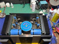
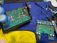
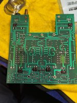
Hi folks, I recently picked up a Krell KSA-50S and completed a comprehensive restoration addressing several known design weaknesses while preserving its original sonic character - maybe improving it. I've upgraded capacitors, improved thermal management, and made several reliability enhancements. I'd love to hear if anyone has additional insights or modifications they've found beneficial for this legendary amplifier.
This thread really outlines the key Achilles heel, the tantalum caps - I replaced all mine with solid polymer. I've been looking for some places to put some boutique special parts, but the way it's designed, it is not the type which would easily take overpriced fancy film caps. Would enjoy the ideas and thoughts. Below is the steps I took and my overall project summary with some justification and rationale.
The following details the complete restoration of a Krell KSA-50S stereo power amplifier, addressing known design weaknesses while maintaining the amplifier's original sonic character. The restoration focuses on modernizing critical components, improving thermal management, and enhancing long-term reliability without compromising the amplifier's legendary performance characteristics.
This restoration preserves the legendary Krell sound while addressing known reliability issues and incorporating modern component technologies where appropriate. The amplifier now offers improved reliability, potentially enhanced sonic performance, and the flexibility to operate in either full Class A (NOR) or more efficient Class A/AB (REL). The careful selection of components respects the original design philosophy while taking advantage of advancements in capacitor technology and thermal management that were not available when the amplifier was originally manufactured.
This thread really outlines the key Achilles heel, the tantalum caps - I replaced all mine with solid polymer. I've been looking for some places to put some boutique special parts, but the way it's designed, it is not the type which would easily take overpriced fancy film caps. Would enjoy the ideas and thoughts. Below is the steps I took and my overall project summary with some justification and rationale.
Krell KSA-50S Comprehensive Restoration Project
Project Overview
The following details the complete restoration of a Krell KSA-50S stereo power amplifier, addressing known design weaknesses while maintaining the amplifier's original sonic character. The restoration focuses on modernizing critical components, improving thermal management, and enhancing long-term reliability without compromising the amplifier's legendary performance characteristics.
Component Replacement Strategy
Capacitor Upgrades
Electrolytic Capacitors
- 22× 470μF/63V: Replaced with Rubycon ZLJ series
- Selected specifically for their high ripple current handling capability
- Superior ESR characteristics compared to original capacitors
- Properly rated for the amplifier's actual operating voltage
- 10× 220μF/63V: Upgraded to KEMET A759 polymer capacitors
- Significantly reduced ESR for cleaner power delivery
- Enhanced temperature stability for long-term reliability
- Polymer technology offers better performance in high-current applications
- 4× 6800μF/16V: Replaced with Cornell Dubilier 6800μF/25V
- Higher voltage rating provides better safety margin
- Improved reliability in high-current applications
- 2× 100μF/100V: Replaced with Chemicon KZN capacitors
- Direct replacements maintaining original specifications
- Reliable performance in high-voltage sections
- 2× 1000μF/10V: Upgraded to Panasonic polymer types
- Reduced ESR for improved power delivery
- Better performance in low-voltage, high-current applications
- 4× 39,000μF/60V: Main filter capacitors to be addressed in future phase
- Currently bypassed with 100nF Vishay MKP1839 film capacitors
- Film bypassing improves transient response across the frequency spectrum
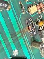
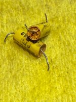
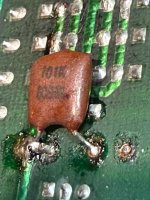
Critical Tantalum Capacitor Replacement
- Suspected design flaw: 10μF/35V tantalums exposed to ~38V (over their voltage rating)
- Creates stress on tantalum capacitors, zener diodes, and voltage regulators
- Potential cascade failure path where one component failure leads to multiple issues
- Explains observed component failures in this amplifier model over time
- Solution: All tantalums replaced with Würth Elektronik WCAP-PTHR 10μF/50V polymer capacitors
- 50V rating provides appropriate headroom for the ~38V they experience
- Polymer technology eliminates the catastrophic failure mode of traditional tantalums
- Modern polymers offer lower ESR and superior reliability
- Enhanced sonic capabilities on the signal board
- Note: 2-3 week burn-in period required for optimal sonic performance
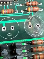
Signal Path Components
- 4× 0.00082μF (820pF) film caps: Replaced with Cornell Dubilier mica capacitors
- Mica provides exceptional linearity and stability
- Added SOCHIN 100pF capacitors in parallel creating 920pF clusters
- Combined configuration offers both precision and vintage "air" in high frequencies
- Improved detail retrieval and transparency in the signal path
- Bypass Capacitors: Added Vishay MKP1839 100nF film capacitors
- Strategic bypassing of the massive filter capacitors
- Enhanced transient response and power supply performance
Protection Components
- 4× 1N4740A (10V) zener diodes: Completely replaced
- 4× 1N4743A (13V) zener diodes: Completely replaced
- 3× Omron relays replaced: 2× DC - LY4-0-DC24, 1× AC - LY4-0-AC120
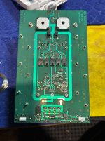
- All protection circuitry fully restored to original specifications - complete tantalum removal and heat sinks added to regulators
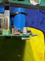
Thermal Management Upgrades
Transistor Thermal Interface Materials
- Power Transistors: Bergquist SP600-02 SIL-PAD premium thermal pads
- 0.35°C/W thermal resistance (exceptional performance)
- 1.0W/m-K thermal conductivity
- Green silicone elastomer without fiberglass backing
- Significantly improved thermal transfer compared to original mica insulators
- Voltage Regulators: Boyd Laconia 7142DG heatsinks with Bergquist SP900S thermal pads
- TO-220 clip-on heatsinks with tin plating for maximum thermal dissipation
- Adhesive-backed thermal pads eliminate need for messy thermal compound
- Improved thermal stability for voltage regulation circuitry
Thermal Interface Materials
- Exclusive use of premium thermal pads: No thermal paste used
- Bergquist SP600-02 for TO-3 transistors (thermal resistivity: 0.35°C/W)
- Bergquist SP900S-0.009-AC-54 with adhesive backing for TO-220 devices
- Superior thermal coupling compared to thermal paste/mica combinations
- Cleaner installation and more consistent performance
Circuit Modifications & Discoveries
Bias Control
- NOR/REL Switch: Identified as bias level control
- NOR = higher bias (4.20V) = full Class A operation
- REL = lower bias (3.85V) = Class A/AB operation
- Set to REL mode for cooler operation and improved reliability
Front Panel Board
- SW1/SW2: Identified front panel board switch functions
- SW2 controls power-on behavior (normal vs. auto power-on)
- SW1 has minimal effect on bias
- Both set to "OPEN" for normal operation
Power Supply Analysis
- True power rail voltage: Actual ±60V vs. schematic-indicated ±45V
- Zener diode network: Provides 24V drop, leaving ~38V at capacitor positions
- Solution: Upgraded capacitor voltage ratings to 50V+ where needed
Technical Findings
Protection Circuit Details
- LM339AN comparator on protection board monitors bias levels
- Custom Krell logic chip (KSA50a v1.4) controls bias indicators and protection
- Speaker relay protection activated by optical isolation circuitry
- SW1/SW2 switches provide customization of power-on behavior and bias monitoring
Performance Measurements
- Bias Voltages:
- NOR mode: 4.20V (full Class A)
- REL mode: 3.85V (Class A/AB)
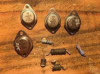
- Output Devices: Original Motorola MJ15024/MJ15025 transistors preserved
- Date Codes: 9410 and 9414 (10th and 14th weeks of 1994)
- Part Numbers: 484025 and 484024 complementary pairs
Expected Sonic Improvements
Capacitor Upgrades
- Polymer capacitors: Significantly lower ESR than original electrolytics resulting in:
- Improved bass definition and control
- Reduced distortion under dynamic conditions
- Better power delivery during transients
- Mica capacitors: Enhanced clarity and detail retrieval in the signal path
- More precise imaging and soundstage presentation
- Improved transparency without harshness
- Properly rated components: Reduced stress on power supply components leading to:
- More consistent performance under varying conditions
- Improved dynamics and transient response
- Sochin capacitors: Adding subtle vintage warmth to high frequencies
- Enhanced spatial presentation
- Richer harmonic presentation without loss of detail
Bias Mode Selection (REL vs NOR)
- REL mode: Produces less heat while sacrificing minimal sound quality
- Extended component life
- Maintains excellent sound quality
- Suitable for long-term listening sessions
- NOR mode: Offers purest Class A operation but with significantly higher thermal stress
- Available for critical listening sessions
- Maximum linearity and transparency
- Best used for shorter listening periods
Future Considerations
Planned Upgrades
- Main Filter Capacitors: Future replacement of the 39,000μF/60V main filter capacitors
- Evaluating options for highest performance and reliability
- Film bypassing currently enhances performance
Fuse Upgrade
- Replace undersized 1A fusewith appropriately rated 5A-8A slow-blow fuse
- Properly sized for the amplifier's actual current draw
- Prevents nuisance tripping during high-power operation
Long-Term Reliability Enhancements
- Monitoring heatsink temperatures in both REL and NOR modes
- Periodic inspection of remaining original capacitors
- Optional implementation of third zener diode as suggested in repair literature
Restoration Methodology
- Premium audio-grade components for signal path positions
- Industrial-grade components with higher ratings for power supply
- Maintaining original design intent while addressing known weaknesses
- Strategic upgrades (polymer, mica) only where beneficial
- Original transistors preserved in their appropriate positions
Conclusion
This restoration preserves the legendary Krell sound while addressing known reliability issues and incorporating modern component technologies where appropriate. The amplifier now offers improved reliability, potentially enhanced sonic performance, and the flexibility to operate in either full Class A (NOR) or more efficient Class A/AB (REL). The careful selection of components respects the original design philosophy while taking advantage of advancements in capacitor technology and thermal management that were not available when the amplifier was originally manufactured.
Attachments
-
 IMG_2414.jpeg880.1 KB · Views: 38
 -
 IMG_2420.jpeg1 MB · Views: 34
 -
 IMG_2421.jpeg942 KB · Views: 36
 -
 IMG_2431.jpeg959.3 KB · Views: 37
 -
 IMG_2428.jpeg875.4 KB · Views: 34
 -
 IMG_2422.jpeg772.7 KB · Views: 36
 -
 IMG_2445.jpeg612.9 KB · Views: 39
 -
 IMG_2448.jpeg826.4 KB · Views: 34
 -
 IMG_2449.jpeg671.5 KB · Views: 32
 -
 IMG_2466.jpeg707.4 KB · Views: 35
 -
 IMG_2469.jpeg602.4 KB · Views: 34
 -
 IMG_2468.jpeg653.8 KB · Views: 31
 -
 IMG_2442.jpeg721.8 KB · Views: 37
Last edited:
Holy Crap. That is a lot of work! NA a suitable amp for Antarctica!
Is that a KSA-50S (Sliding Bias) or KSA-50?
Is that a KSA-50S (Sliding Bias) or KSA-50?
keeps it cool..suitable amp for Antarctica!
50S and I suspect the fading tantalum caps have a lot to do with this system's stability. I also should have noted that the Kyocera RPA RPA0606100M050K make excellent replacements for bulk of the 10uF on form factor and size to rated value. There were two on the control board at 3.3uF I replaced with MLCC X7R- stability, consistency....
- Home
- Amplifiers
- Solid State
- Help repair Krell KSA-50S