I am replacing (ceramic? def. not electrolytic) capacitors in a pair of old MF amps as I have been advised this is where my problem lies. The following is what is printed on the pertinent caps :
Model# on component
Philips 680P F400 KP W 1
Philips 680P f400 KP W1
CGW 220 JIL 650
CGW 220 JIL 650
330 H
Can anyone help me identify what they are?
Model# on component
Philips 680P F400 KP W 1
Philips 680P f400 KP W1
CGW 220 JIL 650
CGW 220 JIL 650
330 H
Can anyone help me identify what they are?
As F is a tolerance code for +/- 1 %, H for +/- 2.5 % and J for +/- 5 %, an as KP stands for polypropylene, probably
Philips 680 pF +/- 1 %, 400 V polypropylene
Philips 680 pF +/- 1 %, 400 V polypropylene
Some sort of 220 pF +/- 5 %, 650 V capacitor
Some sort of 220 pF +/- 5 %, 650 V capacitor
330 pF +/- 2.5 %
Are you sure they are faulty? Decades old paper capacitors are notorious, but these seem to be fairly modern precision capacitors.
Philips 680 pF +/- 1 %, 400 V polypropylene
Philips 680 pF +/- 1 %, 400 V polypropylene
Some sort of 220 pF +/- 5 %, 650 V capacitor
Some sort of 220 pF +/- 5 %, 650 V capacitor
330 pF +/- 2.5 %
Are you sure they are faulty? Decades old paper capacitors are notorious, but these seem to be fairly modern precision capacitors.
I read the same as my fellow countryman.
Why is it with these components "where your problem lies"?
Please elaborate.
Why is it with these components "where your problem lies"?
Please elaborate.
How very kind of you. That really is enormously helpful.
I believe the amps were made in the 1980's and there are no definitive schematics available. I could take out (desolder) all the caps but the track is so flimsy I risk breaking it. I have a problem with the amps in that they don't balance. one monobloc is significantly less loud than the other.
After swapping out all the electrolytics, some cracked zener diodes and several burned out resistors this seems the next best mod...?
I would much rather take a good look at the resistors in the feedback path for that kind of problem.
What model MF are we talking about? Maybe there is a schematic floating about on the interwebs after all.
What model MF are we talking about? Maybe there is a schematic floating about on the interwebs after all.
In case you missed the point earlier, those capacitors are extremely unlikely to be defective
or cause any problems. The person who told you otherwise is surely mistaken. Do not remove them.
or cause any problems. The person who told you otherwise is surely mistaken. Do not remove them.
Absolutely. We can't suggest anything practical without knowing what the design is. Musical Fidelity made lots of models from when it started up in 1982. Some were small class A, most were medium size class AB in BJT and Mosfet flavours. They also had more than their share of manufacturing compromises and resulting faults that customers would later discover.......What model MF are we talking about?.....
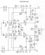
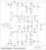
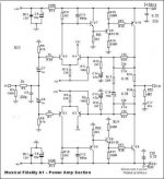
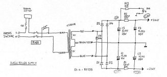
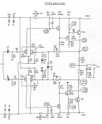 Thanks, all. The amps are MA50 monoblocs. MF built these in the case of the A1 integrated amp. I have understood that the MA50 uses the pair of power amp sections of an A1, the two sides of the amp are bridged (run in anti-phase) to give 50W output. I started at Mark Hennessy's excellent site in 2010 at which point I took his advice and replaced all the electrolytics. This made a huge difference. Since then I found heat-damage to resistors (which I upgraded) and zener diodes which I replaced and have been messing around with them periodically since 2010.
There are about six different schematics available and over the years I have collected (I think) every variant. Some printed, most just hand drawn and photocopied to the point of being blurry. Also, none of these schematics categorically state that they are for the MA50. To add to the confusion, I believe the later vesrsions of the A1 were uprated from 20 to 24/25w per channel so again, those scehmatics would, I assume, have higher rated components too.
I have been looking at everything I can find on line (including photographs of other peoples' MA50s and A1s to try and work out what should be in my amps.
Add to this my meagre but growing knowledge of electronics and I am sometimes like a blind man swimming in a dark lake looking for...well, I don't know!
Any advice is very gratefully received. I will attach the schematics I have...
Ceramic capacitors don't change in value over time unless shiny plate material is exposed, IMHO.
First measure your resistors with the DVM with the power off and electrolytic capacitors discharged. This should help you determine which schematic you have, pointing out glaring errors in the the theory of the diagram you are tracing.
24 w/ch is not a lot and most output transistors should be capable of that easily. Upgrade is probably the size of the heatsink on the output transistors. Heat sinks are high cost items. Report package of output transistors, TO220 3/4" wide or TO247/TO3p an inch wide.
Difference between two of the schematics is that one has a pnp-npn driver-output on one side, emitter follower (matching polarity) on the other side. Other schematic has emitter followers both sides. This is natural as pnp power transistors were more expensive than npn until about 1985? Look for the date code on your power transistors, often YYWW where YY is a 2 digit year starting with 19 and WW is the week produced running from 01 to 53. Late nineties they went to YDDD where Y is 1 digit year and DDD is day from 001 to 366. You can determine polarity of driver transistors with diode check function of dvm, which direction finds two diodes B-E and B-C. With the writing side of transistor facing you and the leads pointed down, B is on the left, C is in the middle. If lozeng shaped metal case transistors, looking at lead side, with the longer distance from the screw to leads towards you, B is on the left.
700 - 800 ma idle current across the output transistor emitter resistors is radically high. Scary high in fact. My amps use ~20 ma.
Last edited:
Many thanks, indianajo.
From previous measurements I know that none of the schematics exactly match the components in my amps. This is why I have also used other peoples' photos - to read their resistors for example!
The output transistors are from 1988 varying weeks 10 to 18 (comfotrtingly all within a small manufacturing period) though that might suggest they're all original and they do get hot. Very hot. They're physically coupled to an aluminium u-section and the case lid which is the heat sink for them. Famously, MF used to warm up pies on them when they had them on test!
Your help is very much appreciated.
Then there are the diodes. What do those random collections of letters and numbers mean? I have spent an hour on the net looking at: 1. Pro-electron numbering scheme. 2. JEDEC numbering scheme. 3. JIS numbering scheme. 4. Manufacturers own schemes. None of it makes much sense. Here are the numbers I have for supposedly identical components: 6A100 and 70 6A2. Given everything I have read there seems nothing that fits these.
Diodes from 1988 are easily checked. One diode scale of DVM look for 450-750 volt drop forwards, 9999 or ---- backwards. Backwards may be lower due to parallel resistances.
You don't have any 3 amp speaker back EMF diodes, so the antisaturation diodes on the LTP (differential input transistors) could be 1n4148 world's cheapest diode. The zener diodes feeding the input stage obviously have to be zener diodes rated 12 v but will measure the same. There is a wattage rating on zeners, the 5 W ones are $.35 and the freight from the parts house is $9 so don't calculate to save a dime on 1.3 w or 3 w ones.
I would suggest measuring resistances from PCB trace to PCB trace to find a bad solder joint causing your volume inbalance. Measuring lead to lead you miss that. You may also measure capacitances below 10 uf that way if you have a capacitance meter or function of the DVM.
Bottom line, this is a stupidly complicated circuit with no idle bias control or adjustment. I'd buy some other board suitable for +-24 and salvage your output transistors. Use new heat sink pads & grease. I don't study 20 W amps so I don't have a list of candidates handy, except the 25 W AX6 derivative at the end of this thread: Retro Amp 50W Single Supply - Page 22 - diyAudio
but a LM3875 board for an IC from e-bay would work. Also LM3886 and tda something IC amps. Those import boards always come without the heat sink to save money and push the listing to the top, so be prepared to buy a heat sink & grease. also the rail filter caps usually. You'll need a drill, drill motor, safety glasses to drill the heat sink. The e-caps ebay boards come with will be **** expect them to last a year, maybe.
You'll need some 1" or 1.5" long screws and nuts plus standoffs to hold the board up off the chassis. If you buy actual threaded standoffs you can get away with 3/8" long screws. I use the long ones and 1/4" air tubing for standoffs, much cheaper after you've bought a $10 100' roll of 1/4 air tubing.`
Last edited:
700 - 800 ma idle current across the output transistor emitter resistors is radically high. Scary high in fact. My amps use ~20 ma.
Isn't it a class-A or almost class-A amplifier? In that case 750 mA quiescent current would be perfectly normal if it is supposed to deliver 9 W in 8 ohm before leaving class A. The rather unusual design with two independent feedback loops with small offsets then also makes more sense to me than when it is supposed to work in class B.
Indianajo. Thank you but as I said I am a novice in electronics and your last post is so far above my head I am afraid I have little hope of understanding it. I really appreciate you trying to help me. And yes, it does seem mad to carry on tinkering with this weird old design, but when they're running right, these amps sound incredible.
MarcelvdG Thank you. Yes these amps are class A - at least for the first part of their output. I think I may have reached the limit of what I can do. I will carry on looking for a dodgy solder joint as Indianajo suggests...wihs me luck!
You wrote something about replacing electrolytics. Did you replace all of the electrolytic capacitors in the signal path, C6, C7, C10, C13 and C14, and are you sure you soldered them properly?
If for whatever reason (for example, dried out electrolytic, or poor soldering when replacing electrolytic capacitors) C6 should work normally but C7 should go open-circuit or the other way around, you would have an amplifier with halved gain that self-destructs at high volumes. That's because the half with working electrolytic then works normally while the other half tries to keep the output close to 0 V.
The same holds for failures in C13 and C14, although C10 would increase the chance that the amplifier would survive high volume settings.
If for whatever reason (for example, dried out electrolytic, or poor soldering when replacing electrolytic capacitors) C6 should work normally but C7 should go open-circuit or the other way around, you would have an amplifier with halved gain that self-destructs at high volumes. That's because the half with working electrolytic then works normally while the other half tries to keep the output close to 0 V.
It's actually more complicated than I just wrote due to C10, but I think the conclusion remains that the gain is reduced and the amplifier is prone to self-destruct at high volumes when one and only one of C6 and C7 goes open circuit.
Marcel is right about likelyhood of you making a bad solder joint. I do so also, hard to stay in practice when I only do electronics in the winter.
Your d9 d10 diodes by the input transistors could be replaced by 1n4148, but your power rectifiers on the transformer-rectifier-filter cap page should be 3 A 400 PIV (volts) rated as 1n5404. This board consumes nearly an amp sitting silent, so ~.9 A load on rectifier diodes for idling. If there are two channels in a chassis (I think you said monoblock) then 1.8A for both channels.
There are a lot better ways in 2019 to get distortion below .1% than class A. I'm listening to my AX6 right now (the thread I posted above), it is really nice. 6 transistors and about 70 wires installed by hand by me; on a board I cut & drilled out of blank stock. No computer, no software, just me, a drill, a soldering iron. & reading glasses. there is a PCB artwork available on that thread, but if I did pay Microsoft's price to stay up to date, ( & software compatible) that pcb wouldn't reuse my 1985 transistors, nor would it fit in my ST120 chassis. The ST120 was a bit of a distortion dog and a burnout queen; just a few tweaks made it sound good and it's reliable too.
Last edited:
Thank you Marcel and Inidi. Marcel: I made the change to the electrolytics in 2012. I removed all of them and replaced and upgraded (wattage and operating temperature). The sheet attached shows what happened then.
In 2015 or thereabouts I was looking back at pictures and it struck me that the burn marks on the circuit board where not due to the high temperature of the output transistors as I had originally thought, but that resistors and zener diodes had been over-heating and the damage could be seen in the photos. So I stripped it out again and replaced and upgraded all the damaged resistors and the zeners in those areas.
Following this, the balance between the two was not right and I looked again at what could have been wrongly installed. It was all good but I decided to change a couple of resistors so that both amps used the same brand and models. I tidied up the fixings for the large power supply capacitors and the resistor that originally sat on the board where the new (much bigger) capacitors now sit. Removing the caps I could clearly see that the resistor which is in series with the power on LED was badly burned in both amps. Again - upgrade and replace. That's where I was when I started this thread because someone had suggested changing ALL the capacitors. That's where you guys came in. Today I have managed to find one or two suspect solder joints and one dry joint (thanks Marcel). It's all back together waiting for me to pluck up courage to plug it all back into my system.
I'll let you know.😕
Attachments
The only thing I am thinkng I should do is make the diodes all the same. I will get some that Indi has suggested before I put power back into the amps.
- Home
- Design & Build
- Parts
- Help: Reading capacitors