Hello, I want to experiment by putting an input transformer in a channel of a Soundcraft 500 mixer. I have read on some other threads where people have done this by removing the first 2 phantom blocking capacitors, and replacing them with a transformer, using the existing holes in the pcb from the caps.
I am just a little confused which wires from the transformer to connect to which hole. Can someone help me out?
I will be taking the transformer from an old Teac mixer. There is 5 wires...Brown, Red, Orange, Yellow, Black
I have attached the schematics from the input amp for the Teac, as well as the schematic for the Soundcraft 500 input channel. The trafo is T1 in the schematic, and the 2 caps are c2 and c3 in the Soundcraft input schematic.
It seems like it should be simple but I would like to get an opinion from someone with more experience..
Thanks !
Attachments
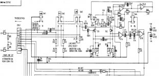
The capacitors are C1 and C2.
What do you want to do this for? There is no advantage just loss of lower frequency response.
If you want, why not use a DI box to isolate an already isolated input?
What do you want to do this for? There is no advantage just loss of lower frequency response.
If you want, why not use a DI box to isolate an already isolated input?
Hello, yes you are right its c1 and c2.. To be honest, I want to do it just out of curiosity ... I also like making funky sounds and I like the color that transformers add, so I want to put a transformer into a channel just for the fun of it to see what it sounds like. If I don't like it I can just switch it back. These are old mixers I just have lying around, so theres nothing to lose. Do you know which colored wires I would add to which hole if I want to do this?
brown and red are primary orange and yellow are secondary black is ground but doing this is going to take more than just dropping in the transformer to make it work right or is that the point...
- Status
- Not open for further replies.