I cant see a 33k vs 68k making that much difference, do you still have the 1meg resistor from the tip to ground connected?
Yeah, and it measure perfectly. The 33K is the grid resistor for the first preamp tube, by the way. My bad!
When I first started the amp, after the tubes warmed up I got a 60hz buzz out of the speaker, followed by several spaced out intermittent pops that made the glow in the 12ax7 respond- it was weird. I turned it off and checked my work, and found out I had wired the output jack wrong (i tied the sleeve and tab instead of the sleeve to ground) so after I fixed that, I got no sound at all from the speaker. Weird?!
Absolutely- I'll check them as soon as I get back to the shop. Thanks again for all your help so far! I think I measured the cathodes on the preamp the other day to be right at 0 volts or so. I will confirm all the voltages tomorrow.
Update: re-measured voltages this morning. 12ax7 DID NOT GLOW during this test- only heater glow. I'll repost all of the exact voltages here- because I've also been working on several other amps and the last figures I gave were only approximate.
5y3: 404 & 408 volts DC out, 335 AC on the plates. Heater voltage at 5.1
6V6: 387 Plate volts, 324 screen volts, cathode at 20V.
12AX7: 184 on pin 1, 187 on pin 2, 1.5 on pin 3, 1.3 on pin 6.
5y3: 404 & 408 volts DC out, 335 AC on the plates. Heater voltage at 5.1
6V6: 387 Plate volts, 324 screen volts, cathode at 20V.
12AX7: 184 on pin 1, 187 on pin 2, 1.5 on pin 3, 1.3 on pin 6.
Don't know how relevant this may be, but I just discovered that the surge protector I've been using has a leaky on/off switch- the light on the strip stays dim even when switched off.. i measured 5 volts AC coming into the mains fuse with both switches off, the amp and the surge protector... When I leave the amp switch on but switch off the surge protector to partially drain the filter caps, the light on the surge protector would cut off- suggesting I was letting 5 volts seep through into my transformer.... Should I be concerned about this?!?!?!?
Update: re-measured voltages this morning. 12ax7 DID NOT GLOW during this test- only heater glow. I'll repost all of the exact voltages here- because I've also been working on several other amps and the last figures I gave were only approximate.
5y3: 404 & 408 volts DC out, 335 AC on the plates. Heater voltage at 5.1
6V6: 387 Plate volts, 324 screen volts, cathode at 20V.
12AX7: 184 on pin 1, 187 on pin 2, 1.5 on pin 3, 1.3 on pin 6.
You shouldn't have 187 volts on pin 2. This pin is referenced to ground so should be at 0v. Also, you should have around 185v on pin 6, not 1.3v. Recheck your measurements or your wiring. Looks like that 187 v on pin 2 should be on pin 6. The 1.3v on pin 6 looks like it should be on pin 8
Last edited:
When I first started the amp, after the tubes warmed up I got a 60hz buzz out of the speaker, followed by several spaced out intermittent pops that made the glow in the 12ax7 respond- it was weird. I turned it off and checked my work, and found out I had wired the output jack wrong (i tied the sleeve and tab instead of the sleeve to ground) so after I fixed that, I got no sound at all from the speaker. Weird?!
Are you sure you fixed it or just created a new and different problem - it sounds like it worked before and now it doesn't..
You shouldn't have 187 volts on pin 2. This pin is referenced to ground so should be at 0v. Also, you should have around 185v on pin 6, not 1.3v. Recheck your measurements or your wiring. Looks like that 187 v on pin 2 should be on pin 6. The 1.3v on pin 6 looks like it should be on pin 8
You're right- I totally meant PLATES 1 and 2, not PINS 1 and 2. Good call!!
Are you sure you fixed it or just created a new and different problem - it sounds like it worked before and now it doesn't..
It certainly does! But, according to the Fender schematic, the Hoffman schematic, and the Hoffman wiring diagram, the first configuration I had was wrong, and this one is correct... Treachery afoot?
Question- should I be able to get continuity between the output transformer primary and secondary...?! Maybe this ot shorted?
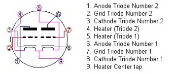
Actually, for some reason, triode #1 is pins 6,7,8 and triode #2 is pins 1,2,3. Pins 1,6 are the plates or in this diagram, called anodes, 2,7 are the grids and 3,8 the cathodes.
No you should not get continuity between pri. and sec. for the OT. You know somewhere during me catching up on this thread(I just started reading it this morning) the thought crossed my mind for a second, did he ruin the OT?. And then I moved on to read more and found those wrong voltages on the 12AX7 and forgot about thinking about the OT being ruined. I think it was post #23 about wiring the output jack wrong.
Glad to see you misspoke about the voltages. In the future, it might be better to refer to a specific pin number so as to limit mistakes like this. Then there will be no doubt.
Last edited:
Dont forget about the negative feedback from the transformer secondary to the cathode of the 12ax7. That could either a) give you continuity when testing between primary and secondary, and b) possibly toast the transformer if the 12ax7 was wired wrong and sent a few hundred volts back that way.
It might be wise to disconnect that feedback loop, then double check the primary and secondary windings are ok.
It might be wise to disconnect that feedback loop, then double check the primary and secondary windings are ok.
It certainly does! But, according to the Fender schematic, the Hoffman schematic, and the Hoffman wiring diagram, the first configuration I had was wrong, and this one is correct... Treachery afoot?
Check to make sure that the jack you are using is identical to the ones in the schematics you referred to.. The fact that you heard hum with the initial hook up indicates that the speaker was probably connected to the secondary and now that you don't it either isn't, you have reversed connections and/or you have a short.
The primary and secondary are completely isolated and given the low dcr of the secondary even if miswired at the 12AX7A there is not going to be enough current available to damage the transformer unless the PSU voltage dropping resistor is not present in which case you would likely blow the primary fuse or fry the rectifier tube.
Dont forget about the negative feedback from the transformer secondary to the cathode of the 12ax7. That could either a) give you continuity when testing between primary and secondary, and b) possibly toast the transformer if the 12ax7 was wired wrong and sent a few hundred volts back that way.
It might be wise to disconnect that feedback loop, then double check the primary and secondary windings are ok.
I took the measurements with the amp turned off- so none of the tubes were conducting thus completing that part of the circuit. so how could it have made connection to the secondary of the OT? Like I'm seriously asking, not playing devil's advocate.
Dont forget about the negative feedback from the transformer secondary to the cathode of the 12ax7. That could either a) give you continuity when testing between primary and secondary, and b) possibly toast the transformer if the 12ax7 was wired wrong and sent a few hundred volts back that way.
It might be wise to disconnect that feedback loop, then double check the primary and secondary windings are ok.
I also fail to see how the NFB resistor connects the two windings. The pri terminates at the plate of the 6V6 on one end , isolating it from further connections. The other end of the pri goes to the first node of the power supply which is isolated from ground by the filter caps, which is the only way to get a path to the secondary. These two windings should not have continuity with each other. If they do, something is wrong with the OT. If I am wrong, please explain the path of continuity to me through the NFB loop.
I think you're right, boobtube. I called ClassicTone about it and I think they're gonna send me another one- I will keep everyone posted!
- Status
- Not open for further replies.
- Home
- Live Sound
- Instruments and Amps
- Help please! 5f1 champ build with No sound!